This thread has been locked.

If you have a related question, please click the "Ask a related question" button in the top right corner. The newly created question will be automatically linked to this question.

LAUNCHXL-CC26X2R1: Cannot Configura WakeUp Pin in Second Task OAD-Off-Chip Example

Part Number: LAUNCHXL-CC26X2R1
Other Parts Discussed in Thread: SYSBIOS

Hello,

I used BLE5Stack OAD Off Chip example and I created a second task to handle all of my customized activities. I keep my second task simple just for trying some little-partial codes like I2C communication or ADC, etc. Now, I am trying "pinShutDown" example like --> one of the buttons is used to shut-down the board (and I can do that) and the other one is used for to wakeup (just before shutting down, I arranged the other button as a wake-up pin) but I could not wake the board up!

NOTE THAT: My hardware has no problem because I tried "pinShutDown" example directly and it worked.

Here is how I added second task (NOTE: I added these codes in "main.c" )

//these codes are added top of the files

#include <xdc/std.h>
#include <ti/sysbios/knl/Task.h>
#include "CustomizationMain.h"


#ifndef TASK_STACK_SIZE
    #define TASK_STACK_SIZE 4096
#endif
#ifndef TASK_PRIORITY
    #define TASK_PRIORITY   4
#endif


/* Task's stack */
uint8_t sbcTaskStack[TASK_STACK_SIZE];

/* Task object (to be constructed) */
Task_Struct task0;

/* Task function */
void taskFunction(UArg arg0, UArg arg1)
{
    PeripheralInit();
    PeripheralRun();
}

Then, I added the code below in the "main()" function just after the line "SimplePeripheral_createTask();" and just before "BIOS_start();" function.

  Task_Params taskParams;

  // Configure task
  Task_Params_init(&taskParams);
  taskParams.stack = sbcTaskStack;
  taskParams.stackSize = TASK_STACK_SIZE;
  taskParams.priority = TASK_PRIORITY;

  Task_construct(&task0, taskFunction, &taskParams, NULL);

Here is my other source code that does not work;

#define SLEEP_MS(a)         usleep(a * 1000)

static bool But1Pressed = false;
static bool But2Pressed = false;

void BigDelay(uint32_t seconds)
 {
     int i = 0;
     int howMany100ms = seconds * 1000 / 100;
     for(i = 0; i < howMany100ms; i++)
         usleep(100000);//100 ms
 }

void gpioButtonFxn1(uint_least8_t index)
{
    GPIO_toggle(CONFIG_GPIO_GLED);
    SLEEP_MS(100);
    if(But1Pressed == false)
        But1Pressed = true;
    else
        But1Pressed = false;
    
}
/* Wake-up Button pin table */
//POWER_SAVING
PIN_Config ButtonTableWakeUp[] = {
    CONFIG_PIN_BTN2 | PIN_INPUT_EN | PIN_PULLUP | PINCC26XX_WAKEUP_NEGEDGE,
    PIN_TERMINATE                                 /* Terminate list */
};

void PeripheralInit(void)
{
    /* Call driver init functions */
    Board_init();

    //pheripheral init here
    GPIO_init();
    GPIO_setConfig(CONFIG_GPIO_RLED, GPIO_CFG_OUTPUT | GPIO_CFG_OUT_HIGH);
    GPIO_setConfig(CONFIG_GPIO_GLED, GPIO_CFG_OUTPUT | GPIO_CFG_OUT_LOW);

    //GPIO Input with Interrupt, configuring input and internal pull-up with falling edge (falling edge can be seen easily in schematic)
    GPIO_setConfig(CONFIG_GPIO_BTN1, GPIO_CFG_IN_PU | GPIO_CFG_IN_INT_FALLING);
    /* install Button callback */
    GPIO_setCallback(CONFIG_GPIO_BTN1, gpioButtonFxn1);
    /* Enable interrupts */
    GPIO_enableInt(CONFIG_GPIO_BTN1);
}


void PeripheralRun(void)
{

    while(1)
    {
        BigDelay(1);
        static int asd = 0;
        Debug_Uart("loopCount: %d", (asd++));
        if(But1Pressed)
        {
            But1Pressed = false;
            Debug_Uart("but1");
            /* Configure DIO for wake up from shutdown */
            PINCC26XX_setWakeup(ButtonTableWakeUp);
            Debug_Uart("LINE: %d", __LINE__);

            GPIO_write(CONFIG_GPIO_RLED, CONFIG_GPIO_LED_OFF);
            GPIO_write(CONFIG_GPIO_GLED, CONFIG_GPIO_LED_OFF);
            Debug_Uart("LINE: %d", __LINE__);

            /* Go to shutdown */
            Power_shutdown(0, 0);
            Debug_Uart("LINE: %d", __LINE__);

            /* Should never get here, since shutdown will reset. */
            while (1)
            {
                Debug_Uart("LINE: %d", __LINE__);
            }
        }
    }
    return;
}

Whit this code, I can see my debug prints, also I can shut-down the board but I CANNOT WAKE IT UP.

I need to wake it up because, in my project, I just used a single button to turn on and off the board.

Please help me with it.

  • Hi Dogus, 

    Assigning an expert to follow-up. 

    Thanks, 
    Elin

  • Hi,

    Thank you. I am waiting for a response then.

  • Hi,

    What is the priority of your newly added task?

    When you say you cannot wake it up, can you be more secific? Does anything happen when you press the button? E.g. how is the power consumption? Can you try attaching the debugger after this happens?

  • Hi,

    Thank you for your reply.

    As you can see the code I shared above, my task's priority is 4. But after you asked, I tried with priority 2 and my problem still exists.

    Normally, my task starts with redLed on and greenLed off state. After I pushed the button1, I toggle greenLed in interrupt routine and in my main function, I sense the button pressed then I turn off both LEDs, configure wake-up-button and shut the device down. After shutting down, I press the button that should wake the device up, there is no activity on my board. I mean, normally, I send some string through UART in each second and I could not see and serial debug prints on my console, also my board starts with redLen on-state but after pressing the wake-up button I could not see my redLed at on-state. Additionally, I searched for my device by using 3rd party application and I could not see my device in active-device-list. I mean, the shutting-down operation seems working good but I cannot wake my board up again with the code above.

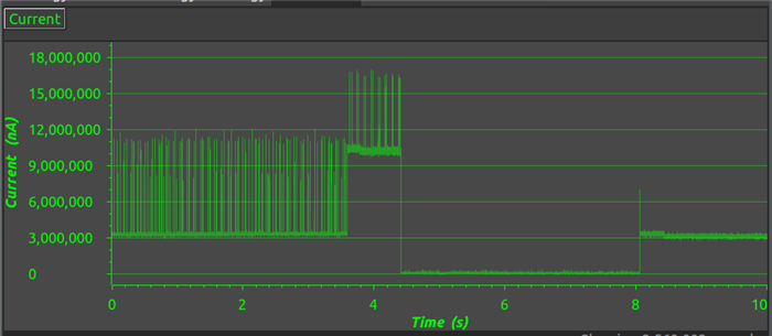
    I just used the Code Composer Studio Energy trace tool to find out my board' s power consumption. Here is the output;

    Actually, the current consumption graph seems promising to me. I pressed button 1 (my shut-down button) at sec: 3,6. Because I turn the greenLed on in my interrupt routine, current consumption jumped to 10mA immediately. After some time, in my main function, I turned both LEDs off and shut the board down at sec: 4,4. After for a while, I pressed the wake-up button at sec: 8 and as you can see, current consumption jumped to 3mA again and it seems logical because as I said, my BLE stack and my LEDs and my UART interface did not work after I pressed the wake-up button but I expect they should work of course.

    I could not get additional debug outputs because when I pressed the shut-down-button while debugging through CCS, I could not see any additional console output like informative or error outputs.

    Thank you for your time, I am waiting for your answer.

    Best regards.

  • Hi, 

    Is there any update on this issue?

    Thanks.

  • Hi,

    Sorry for the late answer.

    Can you try attaching the debugger after this happens? You can find instructions here:

  • Hi dogus,

    Try to implement the Pin Shutdown to the original Off-Chip OAD example program. Also do not use BigDelay() because it is blocking the task, it also might go to Standby Mode.

    -kel

  • Hi Marie,

    In the link you gave, there is an explanation about how to debug but I could not find any explanation on how to get the log, etc. I mean, do you want me to get a log from "Runtime Object View" or you want me to dump the "Registers" tab because there is nothing on the console while I debug. Probably I could not understand exactly what you want as a log. Sorry.

    NOTE: my sdk ver: simplelink_cc13x2_26x2_sdk_3_40_00_02

    Code Composer Studio: Version: 9.2.0.00013

    I added my project as an attachment. It is very basic and it has additional codes that I just wrote them all above, on simple-peripheral-off-chip example. Maybe you help me by using this project.

    texas.zip

    Hi Kel,

    I tried what you said. I mean, I tried removing sleep parts (btw, if I do not use sleep in the second task, my device does not ble broadcast) also I tired that I closed the second task and I implemented my wake-up and power-off codes in SimplePeripheral_init function and problem still exist. My device powers down but waking up.

  • Hi,

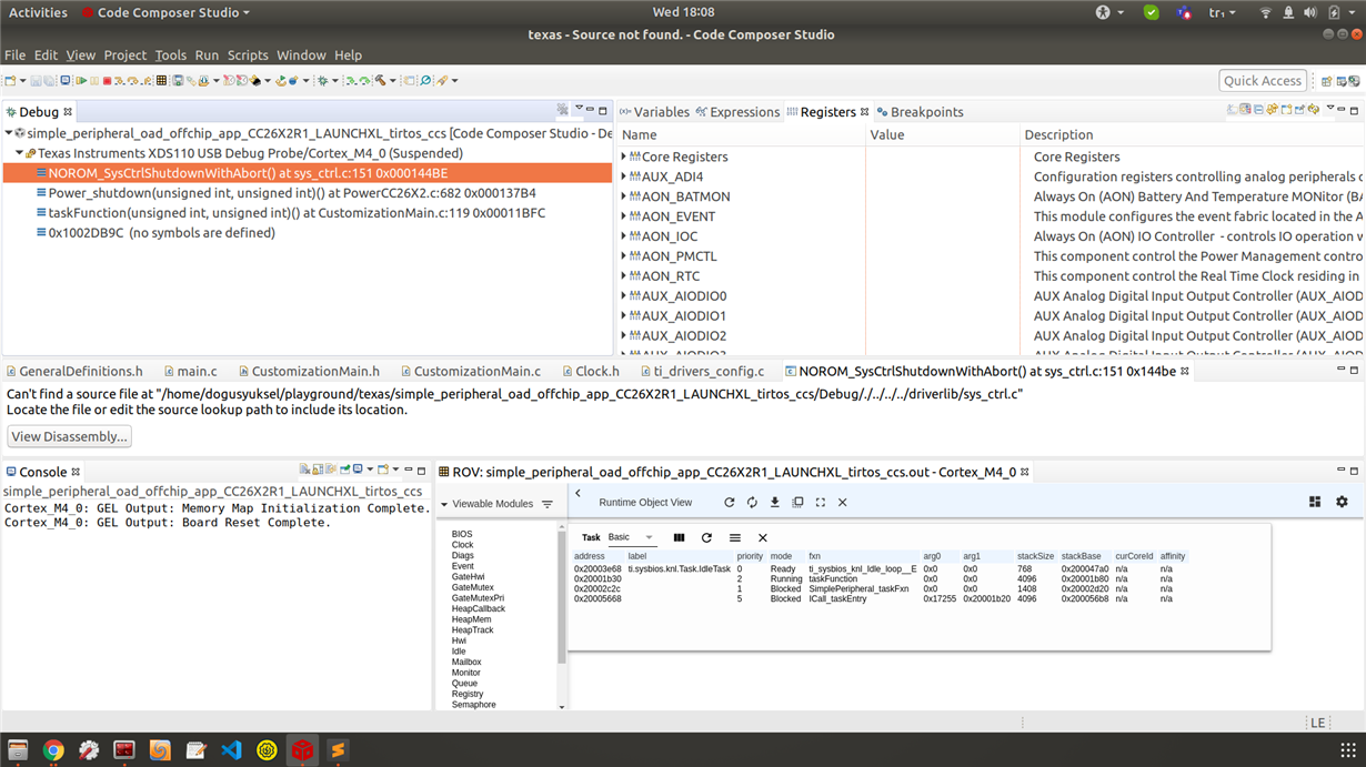
    Can you attach the debugger, then pause the debug session and screen-shot the call stack?

  • Hi Marie,

    I attached the screen. 

    In the attachment, you can see also RuntimeObjectViewver part. When I pressed the button and the system went to power-off, my second task seems "Running". Maybe it can also give a clue to you.

  • Hi Marie,

    Is there any update on this issue?

  • Hi Marie,

    In the meantime, I tried my code (EXACTLY SAME CODE WITH ABOVE) in normal simple_pheripheral example (not oad example) and it worked.

    Just saying, I also loaded "bim" example's hex file with oad_off_chip example's hex file to my device. Normally this procedure (loading bim fw first) is the correct way to use oad_off_chip fw as I know. I do not want to be wrong with this kind of simple mistake. :)

    I am waiting for your feedback, thanks for your time.

  • Hi Marie,

    Is there any update on this issue.

    PS: My custom-designed cards have just arrived so I need to figure out this issue to test my cards (my previous codes and posts are related with the launch board of course, not my custom-designed cards. I just want to notify)

  • dogus yuksel said:
    In the meantime, I tried my code (EXACTLY SAME CODE WITH ABOVE) in normal simple_pheripheral example (not oad example) and it worked.

    The same does not happen with the original off-chip oad example program? You just need to modify the application code.

    -kel

  • Hi Kel,

    Thank you for your reply.

    I am not sure I understand your answer.

    I created this post because I could not wake my board up with "simple_peripheral_oad_offchip example" if I used the code pieces I wrote them down in my first post. But I checked that whether my code is wrong or not, I implemented my code pieces (with exactly the same way I mentioned in my first post) over "simple_peripheral example" and I observed my code is not wrong because wake my board up scenario is worked by implementing my code with "simple_peripheral example".

    NOTE THAT: You can find these examples under this path: <CC13x2 26x2 SDK PATH> -> Examples -> CC26x2R LaunchPad -> BLE5-Stack

    I mean my problem still valid. I need to wake my board up successfully by using "simple_peripheral_oad_offchip" example codebase.

  • Hi,

    Did you configure the wakeup pin in the BIM project too?

  • Hi Marie,

    Thank you for your reply.

    I looked at the bim project and it has a logic like that; it checks external flash and searches a valid image. If there is none, it checks internal flash for a valid image and if there is one, bim code jumps directly to the starting point of it. I mean, bim code returns nothing, just jumps. This logic is valid for my case and in this logic, there is a single GPIO operation making ext_flash CS pin output, nothing more. In my main code, as you know I made my wake-up pin configurations here and shut my device down.

    As far as I know, after a normal wake-up operation, bim should start first and in my case, it jumps to main applications starting point located in the internal flash already and the last application running is my main application, not bim application and I made my wake-up configuration in my main application. I mean, I made my configuration in the last-running-application. Why should I add configuration in bim application, I just need bim to jump my main application, nothing more?

    I guess it is needed to be asked that, after I called to shut down call in my main application, does system jump return to bim application again? If so, there is nothing related GPIO configuration in bim application, and maybe it smashes my GPIO configuration was done in the main application before.

    If this scenario is valid, then how (with what patch) and where should I write my configuration codes in the bim application?

  • Hi Dogus,

    Do you want the device to wake up and run BIM or the application image? For safety reasons I would recommend running BIM when the device wakes up.

    When shut-down is called the device shuts down. It does not jump to BIM.

    Can you do all the GPIO configuration in BIM as well as the application image and retry?

  • Hi,

    Thank you for your reply.

    As you said, I tried to add wake-up configuration to the bim project.

    I added this code part into bim_main.c

    #include <ti/drivers/GPIO.h>
    //#include "ti_drivers_config.h"
    #define CONFIG_PIN_BTN2    0x0000000e
    #include <ti/drivers/Power.h>
    #include <ti/drivers/PIN.h>
    #include <ti/drivers/pin/PINCC26XX.h>
    PIN_Config ButtonTableWakeUpBim[] = {
        CONFIG_PIN_BTN2 | PIN_INPUT_EN | PIN_PULLUP | PINCC26XX_WAKEUP_NEGEDGE,
        PIN_TERMINATE
    };

    Then I called "PINCC26XX_setWakeup(ButtonTableWakeUpBim);" judt before "jumpToPrgEntry(imgHdr.prgEntry);" this jumping code.

    Even if I tried to add all the necessary directories to the project I got this error;

    Description Resource Path Location Type
    unresolved symbol ti_sysbios_family_arm_m3_Hwi_disableFxn__E, first referenced in /home/dogusyuksel/ti/simplelink_cc13x2_26x2_sdk_3_40_00_02/kernel/tirtos/packages/ti/dpl/lib/dpl_cc26x2.aem4f<HwiP_tirtos.oem4f> cc26x2r1lp_bim_offchip C/C++ Problem

    Could you please guide me to compile my bim project successfully.

  • Hi Dogus,

    Hm, the BIM project doesn't use RTOS so I guess that's why you're getting the error. 

    You should still be able to use the GPIO driver, can you look at the nortos version of the GPIO driver example and compare?

  • Hi,

    In the example you shared, I could not see any wake-up configuration. I checked Resource Explorer and I saw pinShutDown example but it was written just for RTOS. 

    If I am not wrong, I need "PINCC26XX_setWakeup" function equivalent. I could not see any equivalent function in GPIO.h also.

  • Hi Dogus,

    Actually I think the easiest would be to use driverlib APIs to configure the pin in BIM. You can use the GPIO driverlib functions:

    A different alternative would be to make your own version of the PIN driver API (PINCC26XX_setWakeup). If you look in PINCC26XX.c you will notice the most essential part of configuring a wakeup pin is the register writes to the IOC register. You could make your own API that configures the pin directly using register writes (HWREG() API).