This thread has been locked.

If you have a related question, please click the "Ask a related question" button in the top right corner. The newly created question will be automatically linked to this question.

CC2640R2F: Power Consumption Difference, why?

Part Number: CC2640R2F


We have some percentage of the final CC2640R2F product, which their power consumption is about 15%~20% more than the other percentages. The software is exactly the same. The hardware is from the same batch of manufacturing, all SMT. It was through ultrasonic processing. Not sure if ultrasonic caused breaking components? If so, what would the most likely component be? The hardware is pretty much the basic from the reference design. Every test conditions were exactly the same.

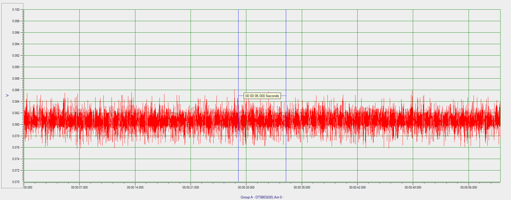
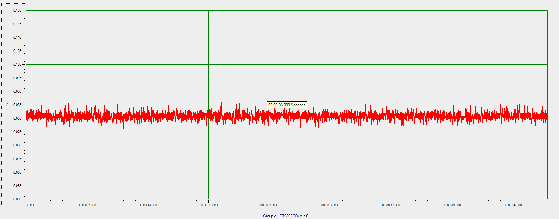
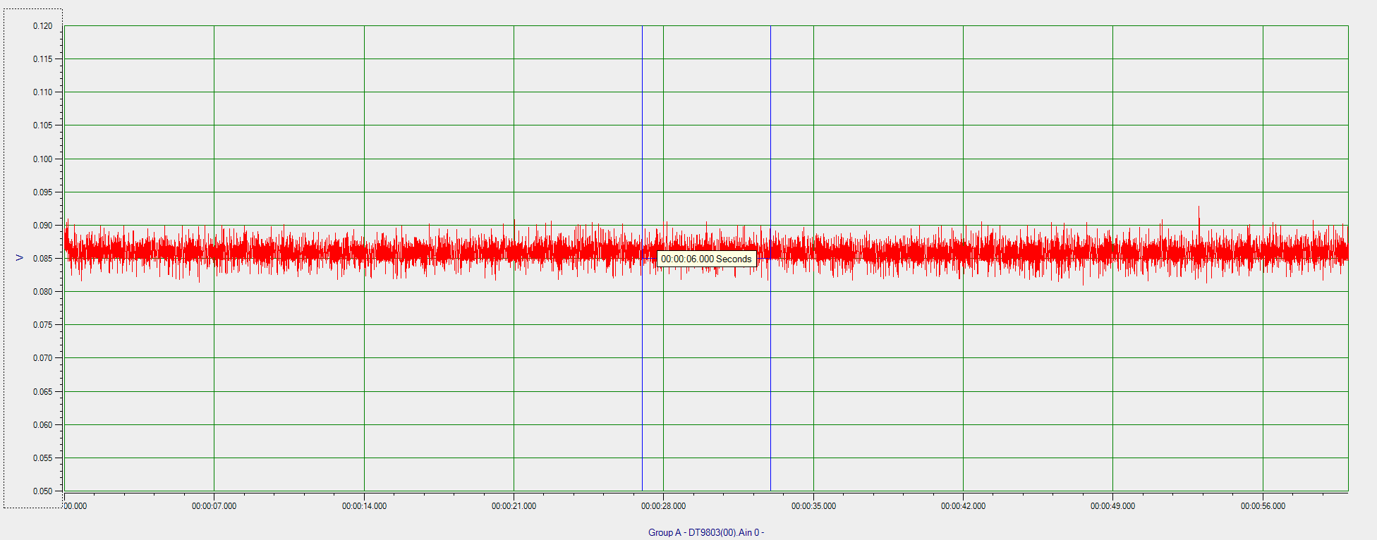
This is the standard consumption:

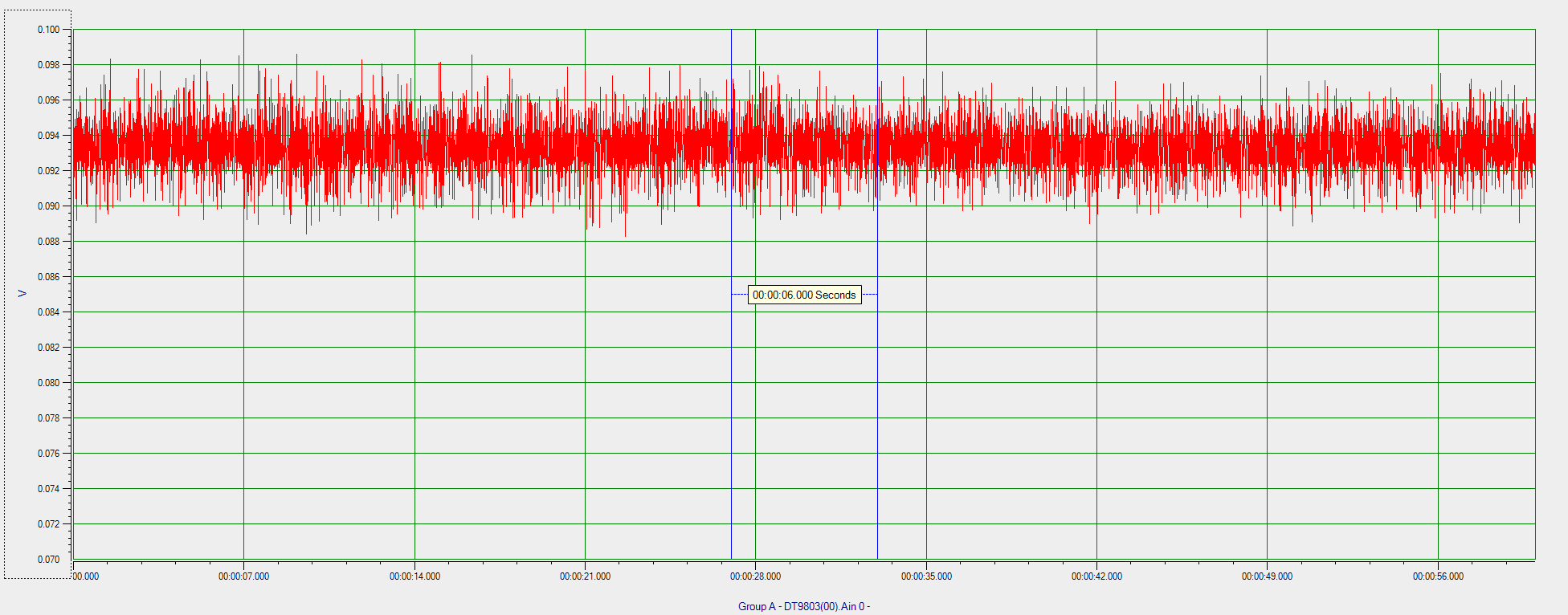
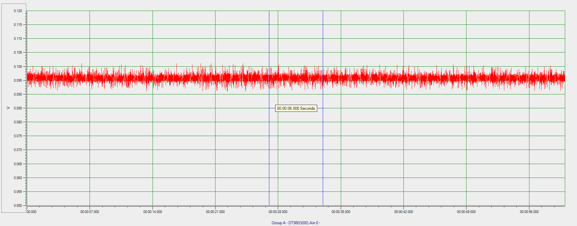
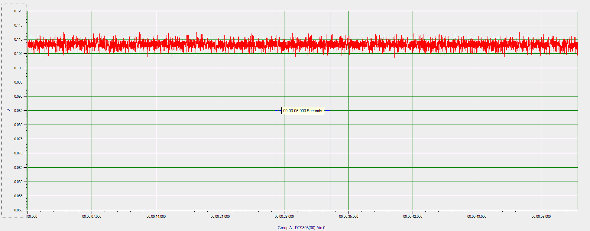
This is the problematic consumption:

Simple schematic:

Samson

  • - Is the y-axis in the plots in mA? Is in number of units on the x-axis? 

    - Which state is the chip in when doing this measurement? 

    - Is it just CC2640R2F on the board or is it other devices on the board that draws current? If the latter, do you know that the CC2640R2F draws current? 

  • Hello TER,

    >>> Is the y-axis in the plots in mA? Is in number of units on the x-axis? 

    The number on the y-axis divide by 10 is the mA number. The x-axis is time.

    >>> Which state is the chip in when doing this measurement? 

    Advertising with interval 600ms to 700ms. That's it. Nothing else.

    >>> Is it just CC2640R2F on the board or is it other devices on the board that draws current? If the latter, do you know that the CC2640R2F draws current?

    There are an external flash and an external sensor. That's it. I am pretty sure these two external components are not the problem source. When CC2640R2F is sleeping, there is zero current drawing. The sensor has its own idle state, it has nothing to do whether CC2640R2F is sleeping or not. So I am pretty sure the current is drawn by CC2640R2F itself only.

    Samson

  • Would it be possible to zoom in on the current draw for one advertising event for a "good" and "bad" device?

    Would it be possible to do the same measurement where you don't have an antenna on the device but terminate in 50 ohm? The increased current could be caused be the antenna being detuned, either due to something on the board or that you have something in the near field when testing. 

  • TER said:

    Would it be possible to zoom in on the current draw for one advertising event for a "good" and "bad" device?

    Would it be possible to do the same measurement where you don't have an antenna on the device but terminate in 50 ohm? The increased current could be caused be the antenna being detuned, either due to something on the board or that you have something in the near field when testing. 

    Hello TER,

    Here are the extra graphs:

    Good ones:

    Bad ones:

    The little pulses on the bottom were the external sensors.

    Samson

  • An additional question: On the zoomed out plots the current looks different for the various advertisement events, I assume that is just the resolution on the plot and not what it actually looks like? 

    If you set the CC2640R2F to send a CW (Use SmartRF Studio or the CW example in the SDK) and measure the current consumption, do you see the same delta in current consumption (to rule out measurement errors) 

  • TER said:

    An additional question: On the zoomed out plots the current looks different for the various advertisement events, I assume that is just the resolution on the plot and not what it actually looks like? 

    If you set the CC2640R2F to send a CW (Use SmartRF Studio or the CW example in the SDK) and measure the current consumption, do you see the same delta in current consumption (to rule out measurement errors) 

    Hello TER,

    You are right that is the resolution. The plots were manually moved so it is hard to make two graphs with the exact same resolution.

    That is a good suggestion. I will change the firmware to the compliance mode to generate CW. The way I did the measurement does not allow me to use SmartRF Studio.

    Samson

  • Hello TER,

    Here are the graphs of 0dbm @ 2440MHz CW with an external power supply. (Battery cannot offer enough current for CW.)

    I also made the Y-axis consistent between graphs.

    The good one:

    The bad one 1:

    The bad one 2:

    Samson

  • Did you double check the power consumption with a multimeter? And did you terminate with 50 ohm? The current variation is larger than I would expect based on the numbers I have seen from our measurements but before looking into it in detail I would like an confirmation that the delta in current is not due to the antenna. 

  • TER said:

    Did you double check the power consumption with a multimeter? And did you terminate with 50 ohm? The current variation is larger than I would expect based on the numbers I have seen from our measurements but before looking into it in detail I would like an confirmation that the delta in current is not due to the antenna. 

    Hello TER,

    Yes, I did check it with a multimeter. It is the same. I can see the RMS value is in the same variations, 8.x to 9.x mA. For the 50 ohms termination, I have a dumb question since I am not an RF expert. We are using the PCB DN007 antenna. (The same as the LaunchPad.) Do you want me to cut the original DN007 antenna and solder a 50 ohms resistor to the GND, then re-measure it?

    Samson

  • Do you have a series cap to the antenna? If so, remove this and place a 50 ohm (or 47 ohm) to ground on the chip side of this. If you can post a snippet on how the schematic looks like (just the few components towards the antenna) and I can be more specific. 

    Could you also test 5 dBm setting to see what the current variation is there? 

  • TER said:

    Do you have a series cap to the antenna? If so, remove this and place a 50 ohm (or 47 ohm) to ground on the chip side of this. If you can post a snippet on how the schematic looks like (just the few components towards the antenna) and I can be more specific. 

    Could you also test 5 dBm setting to see what the current variation is there? 

    Hello TER,

    Thank you so much for your help.

    These are all mass-produced products, so there is no antenna connector on it. (That is also why its various power consumption is annoyed.) 

    Here are the layout and schematic of the antenna. I will test the 5dbm output later today.

    Samson

  • If you put a 47 ohm resistor as C27 and remove L3 you have in effect terminated with 50 ohm without doing any cutting or large changes to the design. 

  • TER said:

    If you put a 47 ohm resistor as C27 and remove L3 you have in effect terminated with 50 ohm without doing any cutting or large changes to the design. 

    Hello TER,

    I will see if the factory can help me with that. 0201 component size is really too small for me to do it. I need to measure the power again with the 50 ohms termination, right?

    I redo the measurements. The previous graph was 5dbm already, but that has something else, so I did everything again.

    This time, I am pretty sure the external flash and the external sensor are all disabled and all y-axis resolutions are synced. The interesting thing is the 5dbm output made the variation even more.

    All CW 2440Mhz.

    RMS Reading:

    0dbm,

    the good one: 8.18mA

    the bad one: 8.54mA

    the second bad one: 8.64mA

    5dbm,

    the good one: 10.31mA

    the bad one: 10.99mA

    the second bad one: 10.67mA

    0dbm, the good one:

    0dbm, the bad one 1

    0dbm, the second bad one

    5dbm, the good one

    5dbm, the bad one

    5dbm, the second bad one

    Samson

  • TER said:

    If you put a 47 ohm resistor as C27 and remove L3 you have in effect terminated with 50 ohm without doing any cutting or large changes to the design. 

    Hello TER,

    Just a very quick question for me as a non-RF person. The reason to use the 47 ohms termination is to eliminate the problem caused by the antenna, right? If so, they are all simple PCB antennas, is it really possible that antenna is the root cause when they all look the same?

    Samson

  • The power consumption in TX is dependent on the load the PA sees. That means that the current measured should be close to the datasheet values with a 50 ohm termination but could be higher or lower dependent on where the load is in the smith chart. A PCB antenna could present a load that changes if something is close to the antenna (and hence give a current variation) and I would like to remove this variation to see if the current consumption variation you see is caused by the antenna or something else. 

  • TER said:

    The power consumption in TX is dependent on the load the PA sees. That means that the current measured should be close to the datasheet values with a 50 ohm termination but could be higher or lower dependent on where the load is in the smith chart. A PCB antenna could present a load that changes if something is close to the antenna (and hence give a current variation) and I would like to remove this variation to see if the current consumption variation you see is caused by the antenna or something else. 

    Thanks, I have ordered the SMD 0201 47 resistors. That is not something I always have in my hands.

    Samson