This thread has been locked.

If you have a related question, please click the "Ask a related question" button in the top right corner. The newly created question will be automatically linked to this question.

CCS/LAUNCHXL-CC26X2R1: Migration From CC2652 To CC2642

Part Number: LAUNCHXL-CC26X2R1
Other Parts Discussed in Thread: UNIFLASH, , CC2642R

Tool/software: Code Composer Studio

Hi,

I am getting trouble making OAD_OffChip example work on my custom board. As I said, my custom board has 2642R2 MCU and my custom board has no hardware problem because I already tried a lot of examples and they worked on my board including SimplePeripheral example but I need OAD_OffChip example for my project.

I already tried this link: http://dev.ti.com/tirex/explore/content/simplelink_cc13x2_26x2_sdk_4_10_00_78/docs/ble5stack/ble_user_guide/html/cc13x2_26x2/custom-hardware-cc13x2_26x2.html#change-device-configuration and I changed the project variant in CCS. With this, I just accomplished that SimplePeripheral example works on my board now but I could not make OAD_OffChip example work.

I have three questions;
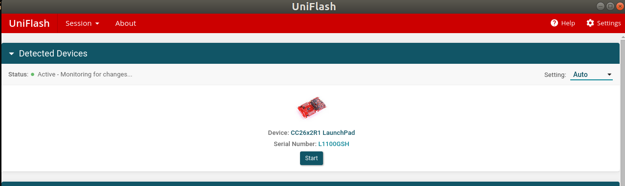
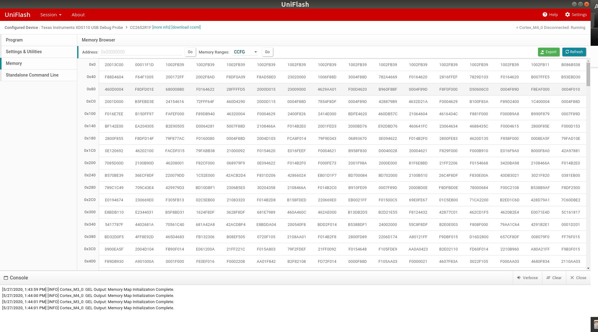
1. with original launch board, I used Uniflash to load my code on the board by selecting "LAUNCHXL-CC26X2R1" option and I select ".hex" files to be loaded but now, I select my MCU first in Uniflash program then I select the debugger. With this configuration, the hex files are not working, only "out" files are working. Why is that? (I am talking SimplePeripheral example now)

2. Even if I changed my bim and OAD_OffChip projects' variant in CCS for both projects, these examples are not working on my custom board. I already tried different hex or out file combinations. What should I do?

3. As I said, SimplePeripheral example works on my board with uploading out file via Uniflash and also realtime debugging via CCS. But the OAD_OffChip example is not working also with realtime debugging option with CCS. I already tried to decrease debugger frequency (I read this solution from your blog also). How should I debug my board with OAD_OffChip example.

I think, the solution of 2 and 3 questions will be same if we can figure it out.

For question 3, I got the error below;

--> Cortex_M4_0: JTAG Communication Error: (Error -1170 @ 0x0) Unable to access the DAP. Reset the device, and retry the operation. If the error persists, confirm configuration, power-cycle the board, and/or try more reliable JTAG settings (e.g. lower TCLK). (Emulation package 9.1.0.00001)

-->Cortex_M4_0: Failed to remove the debug state from the target before disconnecting. There may still be breakpoint op-codes embedded in program memory. It is recommended that you reset the emulator before you connect and reload your program before you continue debugging

Please help me with that.

  • If you use Flash Programmer 2, can it recognize your custom board?

  • There is only windows installer (http://www.ti.com/tool/download/FLASH-PROGRAMMER-2) for this program so I could not do that, I am using Ubuntu OS.

    There is a "Test Connection" button inside "targetConfiguration" in the CCS project. If I use this, there is no error occurred. The output of the test is placed at the end of this post.

    I maybe need to change some additional configuration inside "targetConfiguration" part like "initialization script" or "Access Port Designator" I do not know.

    OUTPUT

    [Start: Texas Instruments XDS110 USB Debug Probe]

    Execute the command:

    %ccs_base%/common/uscif/dbgjtag -f %boarddatafile% -rv -o -S integrity

    [Result]


    -----[Print the board config pathname(s)]------------------------------------

    /home/dogusyuksel/.ti/ccs920/0/0/BrdDat/
    testBoard.dat

    -----[Print the reset-command software log-file]-----------------------------

    This utility has selected a 100- or 510-class product.
    This utility will load the adapter 'libjioxds110.so'.
    The library build date was 'Feb 13 2020'.
    The library build time was '18:03:38'.
    The library package version is '9.1.0.00001'.
    The library component version is '35.35.0.0'.
    The controller does not use a programmable FPGA.
    The controller has a version number of '5' (0x00000005).
    The controller has an insertion length of '0' (0x00000000).
    This utility will attempt to reset the controller.
    This utility has successfully reset the controller.

    -----[Print the reset-command hardware log-file]-----------------------------

    The scan-path will be reset by toggling the JTAG TRST signal.
    The controller is the XDS110 with USB interface.
    The link from controller to target is direct (without cable).
    The software is configured for XDS110 features.
    The controller cannot monitor the value on the EMU[0] pin.
    The controller cannot monitor the value on the EMU[1] pin.
    The controller cannot control the timing on output pins.
    The controller cannot control the timing on input pins.
    The scan-path link-delay has been set to exactly '0' (0x0000).

    -----[Perform the Integrity scan-test on the JTAG IR]------------------------

    This test will use blocks of 64 32-bit words.
    This test will be applied just once.

    Do a test using 0xFFFFFFFF.
    Scan tests: 1, skipped: 0, failed: 0
    Do a test using 0x00000000.
    Scan tests: 2, skipped: 0, failed: 0
    Do a test using 0xFE03E0E2.
    Scan tests: 3, skipped: 0, failed: 0
    Do a test using 0x01FC1F1D.
    Scan tests: 4, skipped: 0, failed: 0
    Do a test using 0x5533CCAA.
    Scan tests: 5, skipped: 0, failed: 0
    Do a test using 0xAACC3355.
    Scan tests: 6, skipped: 0, failed: 0
    All of the values were scanned correctly.

    The JTAG IR Integrity scan-test has succeeded.

    -----[Perform the Integrity scan-test on the JTAG DR]------------------------

    This test will use blocks of 64 32-bit words.
    This test will be applied just once.

    Do a test using 0xFFFFFFFF.
    Scan tests: 1, skipped: 0, failed: 0
    Do a test using 0x00000000.
    Scan tests: 2, skipped: 0, failed: 0
    Do a test using 0xFE03E0E2.
    Scan tests: 3, skipped: 0, failed: 0
    Do a test using 0x01FC1F1D.
    Scan tests: 4, skipped: 0, failed: 0
    Do a test using 0x5533CCAA.
    Scan tests: 5, skipped: 0, failed: 0
    Do a test using 0xAACC3355.
    Scan tests: 6, skipped: 0, failed: 0
    All of the values were scanned correctly.

    The JTAG DR Integrity scan-test has succeeded.

    [End: Texas Instruments XDS110 USB Debug Probe]

  • For Linux system, you can try to use Uniflash to check if it can recognize your board.

  • Hi,

    Here is the screenshot of Uniflash.

  • Hi,

    As you can see from the image I sent previously, Uniflash Detected my board CC26X2R1 LauncPad. Does it seem correct to you?

  • This page only means it detects your XDS110. What if you click start and try to read flash data from your CC2642R?

  • Hi,

    Here is a screenshot from Uniflash -> Memory -> Read Target Device. There is no problem seen while reading.

  • What do you see now if you try CCS again?

  • You mean "try to debug OAD_OffChip example via CCS"? If so, there is still the same problem.

  • If you download and debug the same code on TI launchpad, does it work?

  • I just try it now and it worked with SAME project.

    NOTE THAT: Since I tried with the same project, It means I did not change variant (variant is CC2462R, not 2652R) and it worked on launch board. I believe we missed something while changing the variant.

  • Hi,

    Is there any update on this?

  • Hi,

    There is an update. I directly change my custom board's MCU with LaunchBoard' s MCU. As you know it is pintopin. Then, of course, I expected my card to work with OAD example but NO. I did not work. I got same error.

    Actually I am disappointed because my board has Almost Exactly the same schematic with the launch board. I mean the only difference is the External Flash CS pin.

    NOTE THAT: My problem is NOT "OAD_Example not working" because of the CS pin, of course the example will not work directly I know it, My problem -> I cannot Debug my card with CCS. When I pressed "|> Run" button, I got errors just like I mentioned in my first post.

    Here are the schematics of my custom board. Maybe you see a debug interface hardware problem etc.  Any comment is valuable because I am stuck.

  • Hi,

    I am really stuck right now.

    I said that with Uniflash, the generated hex file is not working, only out file is working. I do not know why but I figured out that when there is reset or on/of my card, my card is not working I mean there is something like my previously uploaded binary was erased from internal flash. I cannot understand.

    Please help me with it.

  • How Launch Board's debugger part supply voltage to my external card (please see the image in my first post)? I do not think 3v3 volt pin does that because I plugged out 3v3 but I can still upload the code by uniflash and my card works. How could it be possible? I am really confused.

  • Hi Dogus, 

    Have you had anyone at TI review your design before manufacturing it?

    Can you also please clarify the question in your last post?

    Thanks, 
    Elin

  • Hi,

    I am trying to maintain my startup and I am losing my test users, I am really stuck now.

    I did not know TI can review my board. Please but please guide me to review my board.

    I am really confused about my problem. Here are the things I have problems about;

    - Firstly, I have a custom board with CC2642R1 MCU. As you can see from my previous post schematic, my schematic is almost same as the launch board.

    - I need to make OAD OffChip example works on my board but I could not. I could debug TI Driver->UartEcho example, I could debug BLE5Stack->SimplePeripheral example but I could NOT debug OAD_OffChip example. CCS seems to load the code but when I pressed RUN button I got errors. (NOTE THAT I can debug this example on original launch board). While I said "debug", I meant real debug property in CCS. Here is my CCS console output;

    IcePick_C: Warning: A firmware update is required for the XDS110 probe. The current firmware is version 2.3.0.18. The probe must be upgraded to firmware version 3.0.0.11 to be compatible with this software. Click the "Update" button to update the firmware. DO NOT UNPLUG THE DEBUG PROBE DURING THE UPDATE. (Emulation package 9.1.0.00001)
    Cortex_M4_0: GEL Output: Memory Map Initialization Complete.
    Cortex_M4_0: GEL Output: Board Reset Complete.
    Cortex_M4_0: Symbol Manager: the object file contains invalid call frame information at .debug_frame 0xf5a0; the rest of call frame information will be skipped. Callstack may not be unwound properly.
    Cortex_M4_0: Error: (Error -1170 @ 0x0) Unable to access the DAP. Reset the device, and retry the operation. If error persists, confirm configuration, power-cycle the board, and/or try more reliable JTAG settings (e.g. lower TCLK). (Emulation package 9.1.0.00001)
    Cortex_M4_0: Trouble Halting Target CPU: (Error -2064 @ 0x0) Unable to read device status. Reset the device, and retry the operation. If the error persists, confirm configuration, power-cycle the board, and/or try more reliable JTAG settings (e.g. lower TCLK). (Emulation package 9.1.0.00001)

    - NOTE THAT: There is no peripheral schematic problem on my custom board because I already make my all peripherals work eg: SPI External flash, I2C RTC, Motion sensor, ADC, GPIO Push-button etc.

    - Then I remove CC2642R1 MCU from my custom board then solder CC2652 (I removed it from launch board) MCU on my custom board. Because I suspected from "properties -> general -> variant configuration" of the project but after changing MCU, I eliminated this configuration problem suspect. Because I faced the same problems with that.

    - There is another thing that, normally I used to upload HEX file via Uniflash to my launchboard and after power off and on, firmware continues to work normally as expected but for my custom board, I cannot load HEX file via Uniflash. I mean, actually I load hex file successfully ( I compared hex file content and uniflash -> memory -> Read Target Content and they matched) but the code is not worked/executed on my custom board. I do not know why.

    - Then I tried to load OUT file, not hex file by using uniflash, then IT WORKS but after power off and on the device then firmware does not work/execute anymore. I again do not know why.

    What is the difference between out and hex file. How does debuuger behave for hex and out files?

    Please make comments on my problems.

  • Hi,

    If you want, let us try to make my board work with HEX file only. To do that, I guess we need to try launch board first. How can I FULLY ISOLATE launch board MCU side and how can I make it work with HEX file with EXTERNAL POWER SUPPLY?

  • Hi,

    Do not you have any feedback?