This thread has been locked.

If you have a related question, please click the "Ask a related question" button in the top right corner. The newly created question will be automatically linked to this question.

CC2642R: GPIO connecting EN pins

Part Number: CC2642R
Other Parts Discussed in Thread: TPS63900, TPS63802

Many regulators (e.g., TPS63900),  has an EN pin, which we cannot let floating. We are intended to connect MCU GPIO to this EN pin so we can enable and disable them as we wanted. We see two problems in doing that;

1) at time T=0 (when we turn ON the device), the GPIO pins are in the high Z state. Due to this at T=0, EN pin will be floating. 

2) when we go into reset pin held mode, the GPIOs will be floating and will make EN pin floating as well. 

I have two questions:

1) How to solve this problem? 

2) If there is no way to solve this problem, can we get away by leaving TPS63900 EN floating? Will we face any issue by leaving TPS63900 floating?

Note: we are using TPS63900 and TPS63802 in our design,, so all the above questions are applicable for both these regulators.

  • Hi,

    We will look into it and get back to you ASAP. Please bear with us.

    Thanks,

    PM

  • Hi,

    Connect Enable to High (to supply voltage) on both devices. That means these devices are ON all the time.

    You can put CC2642 into Sleep mode to conserve power, when it is not is use .


    Thanks,

    PM

  • hi PM,

    since our product is battery operated, we prefer to have a pulldown resistor to turn these devices OFF by default. is it ok if we do that?

  • Hi,

    How would you enable the Regulator?

    Does it controlled by other chip (other than CC2642)?

    You can share the Schematic in PDF for our review, when it ready. We will review and provide you our feedback.

    Thanks,

    PM

  • Hi PM,

    I have requested to add you to this forum. Please accept it. Once the schematic is complete, I will message you.

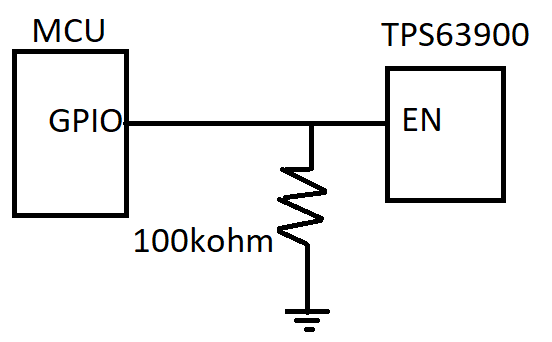
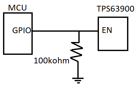
    My idea is given in the figure below. I'm planning to connect the regulator EN pin direct to the GPIO and then have a weak pull-up (100k resistor) connected between the EN pin and the Ground. At Time = 0s and when the MCU is in reset pin held mode, the GPIO will be in high impedance state. During this period, the EN pin will be pulled down by the 100k resistor, and the regulator will be off. Will this idea work?

  • Hi,

    How do you Power-Up the MCU? I want to see your Power Supply circuit to MCU.

    I already accepted your Friend request. If you want we can close this thread and we can communicate through a Friend channel.

    Thanks,

    PM