This thread has been locked.

If you have a related question, please click the "Ask a related question" button in the top right corner. The newly created question will be automatically linked to this question.

CC2640R2F: Flashing MCU only (no Launchpad) through UART - Minimum Required Components?

Part Number: CC2640R2F
Other Parts Discussed in Thread: CC2640,

Hi,

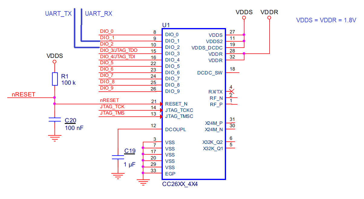
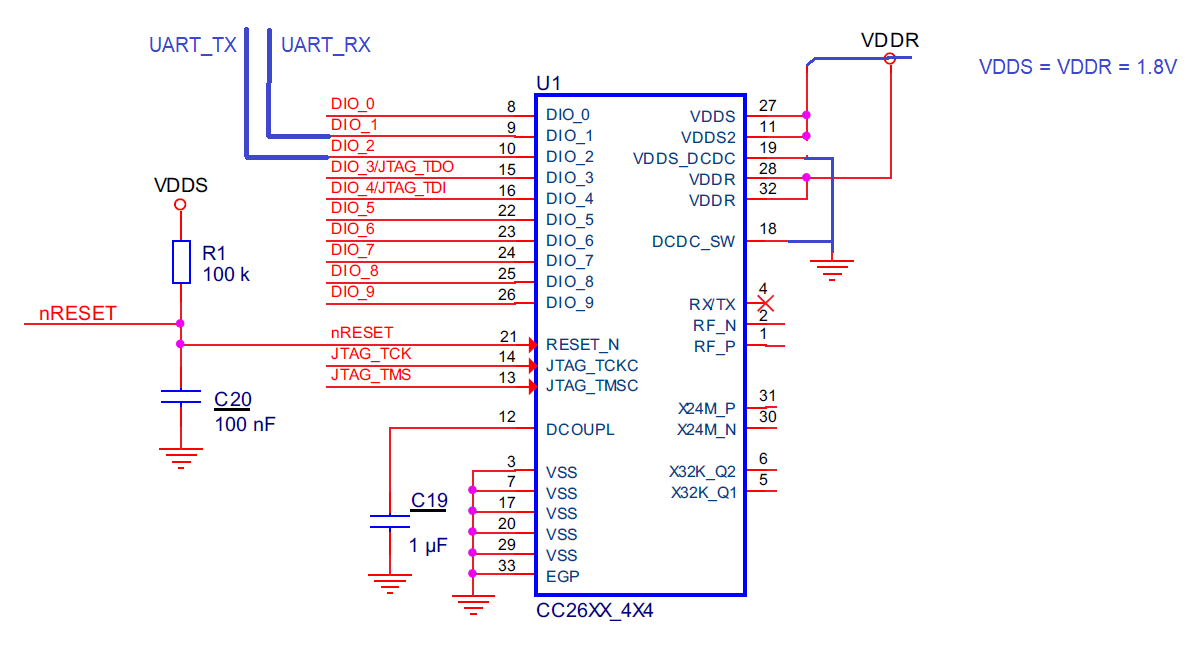
I plan to flash my own cc2640 MCU in-house. I have developed my application with a LaunchPad, but now I would like to flash a cc2640 MCU with the program I developed. I have a socket for the MCU that allows me to easily connect the necessary pins to my XDS110 debug probe. I would like to flash using UART, using the Serial Bootloader Library in Microsoft Visual C++. 

What is the minimum layout for connections/components required to just FLASH the chip with my XDS110? Could I just connect the UART TX and RX , or do I have to connect a VDDS and GND as well, or do I have to implement the entire minimum component layout shown in the datasheet in order to be able to flash the chip?

Thanks!

Ali

  • Why do you want to program the MCU in a test jig before mounting the part on the PCB? Why not program the part after you have placed the device on the PCB?

    You need to power the device, including the VDDR connection according to the power configuration you want to use, the cap on DCOUPL and reset connection.

  • Hi,

    For a bit of context the reason we would like to flash in a test jig before mounting the part on the PCB is because our custom PCB is very space optimized and small so connecting these pins externally to like an XDS110 would be very difficult. Below is the schematic I understood from your explanation. Would this be enough to flash? We would supply VDDS and VDDR with the same 1.8V power, we would supply common ground and then have two pins from DIO_1 and DIO_2 (which I believe are the UART TX and RX for the 4x4 2640 package) to connect to the XDS110 which we would then use to flash either with Serial Bootloader Library or Flash Programmer 2. Is the following schematic correct? So we wouldn't need either crystal, any of the antenna components, and no decoupling capacitor networks? 

    Thanks so much!

    Ali

  • Hi,

    From what I know there are production programmers, that can do this. See, this link below.

    https://e2e.ti.com/support/wireless-connectivity/bluetooth/f/538/t/905562

    But, you still need UART for Bluetooth Qualification testing, so TI TER suggestion is a more better and cheaper way. A jig would have pins that will be in contact with the UART pins and GND, then do the production programming using SmartRF Flash Programmer2 CLI, you can do this automated using Custom Labview or Visual C++ program.

    -kel

  • Hi Kel,

    This is a great link, thank you. Always great to have options. As for your comment regarding TER's answer, this is exactly what I am thinking as well. I just wanted to make sure what components and connections are necessary for me to connect to the jig pins in order to be able to flash with UART. I know the 2 UART pins are necessary, and TER mentioned that I would need the capacitors on DCOUPL and RESET as well in order to flash with UART, as well as connecting a power source and GND. So I was wondering if the schematic I drew in my above reply was correct?

    Thanks so much!

    Ali 

  • Hi,

    TI TER, can provide better reply,

    I am not sure if the schematic is intentionally lacking, but your missing a lot of circuitry. Refer to TI Reference Designs such as the CC2640R2F Launchpad.

    -kel

  • Hi Kel,

    Gotcha, I will wait for TER's reply. I intentially removed a lot of the circuity because this is just for my jig, not my actual final PCB. I'm trying to determine the minimum schematic necessary to be able to flash the cc2640 using UART ports.

    Thanks!

    Ali

  • If you intend to connect VDDS and VDDR to 1.8 V, see https://www.ti.com/lit/an/swra498/swra498.pdf for the required configuration. 

  •  Hi,

    Understood. I updated the schematic accordingly, is the image below accurate? So just to make sure, neither crystal is necessary in order to flash the chip with UART? 

    Thanks so much!

  • I believe that should work in a programming jig. What you can do to be on the safe side is to follow the reference design for external regulator mode but leave the components not in your above figure as DNM which enables you to adjust the BOM if needed.