


Part Number: CC2541
Hi,
My customer has some questions about the reset pin of CC2541 after he check the reference design : CC2541 SensorTag Reference Design 1.4 (Rev. B)
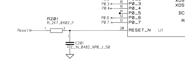
1/ Reset terminal (at R201#1)= Floating/open, R201(V) & C201(V), can system reset okay?
2/ Reset terminal (at R201#1)= Floating/open, R201(V) & C201(X), can system reset okay?
3/ Reset terminal (at R201#1)= Floating/open, R201(X) & C201(V), can system reset okay?
4/ Reset terminal (at R201#1)= Floating/open, R201(X) & C201(X), can system reset okay?
5/ Reset terminal (at R201#1)= VDD, R201(V) & C201(V), can system reset okay?
6/ Reset terminal (at R201#1)= VDD, R201(V) & C201(X), can system reset okay?
7/ Reset terminal (at R201#1)= VDD, R201(X) & C201(V), can system reset okay?
8/ Reset terminal (at R201#1)= VDD, R201(X) & C201(X), can system reset okay?
9/ C201 must be used?
10/ For flash programming pins: RESET_N, SLC, SDA.
How should they be connected when chip is in normal operation?
e.g. RESET_N, SLC, SDA are all floating/open okay?
Please help to provide comments, thanks.
