This thread has been locked.

If you have a related question, please click the "Ask a related question" button in the top right corner. The newly created question will be automatically linked to this question.

CCS/LAUNCHXL-CC26X2R1: Compiling host test for a custom board

Part Number: LAUNCHXL-CC26X2R1
Other Parts Discussed in Thread: SYSCONFIG, CC2640R2F, CC2652RB

Tool/software: Code Composer Studio

I try now to compile Host_Test_CC2642R1 sdk_4_30_00_54 for a custom board.

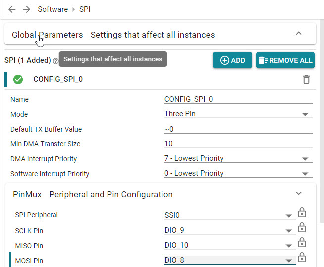
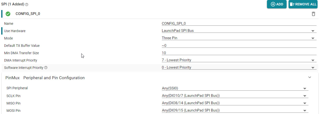
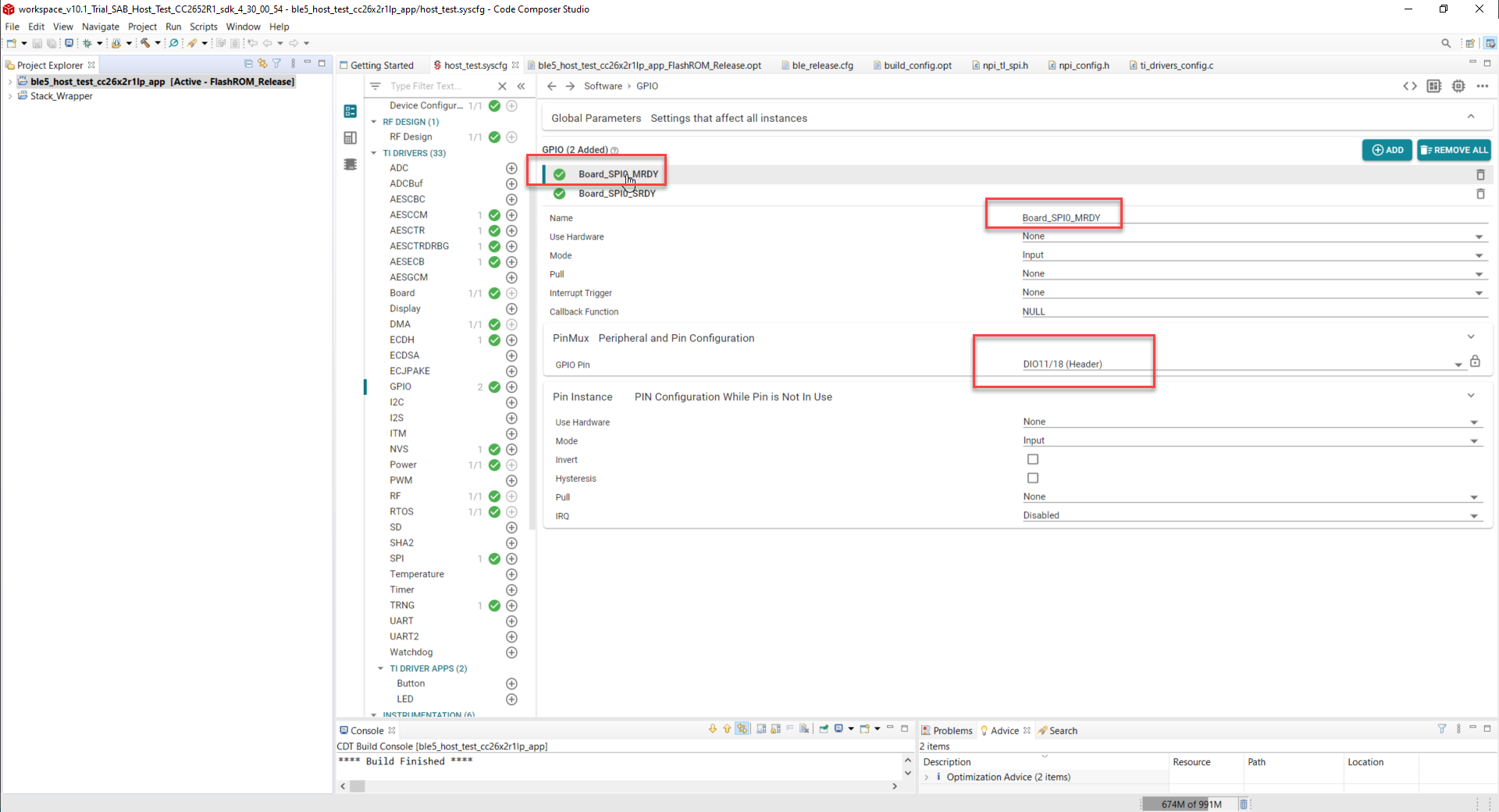
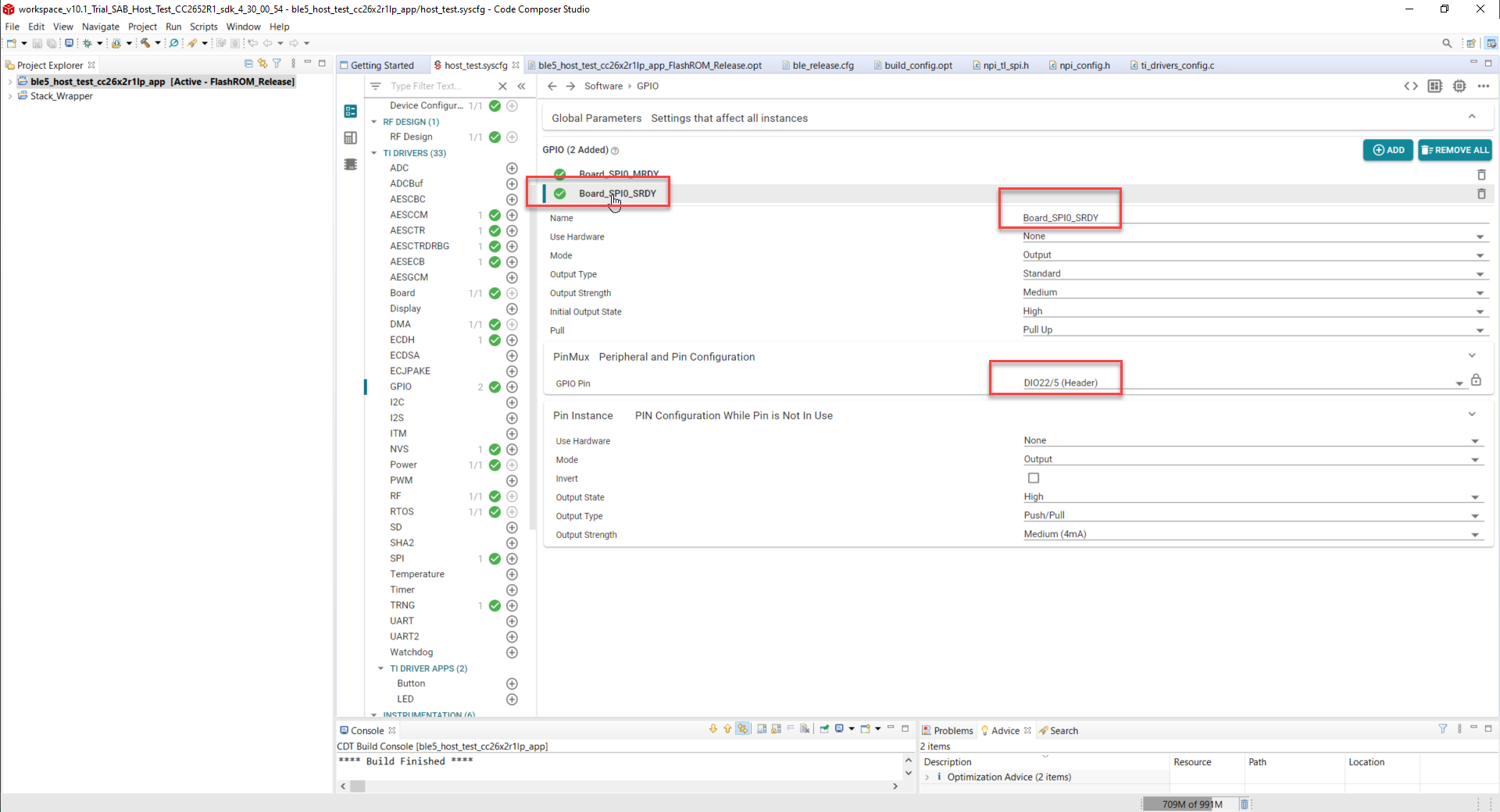
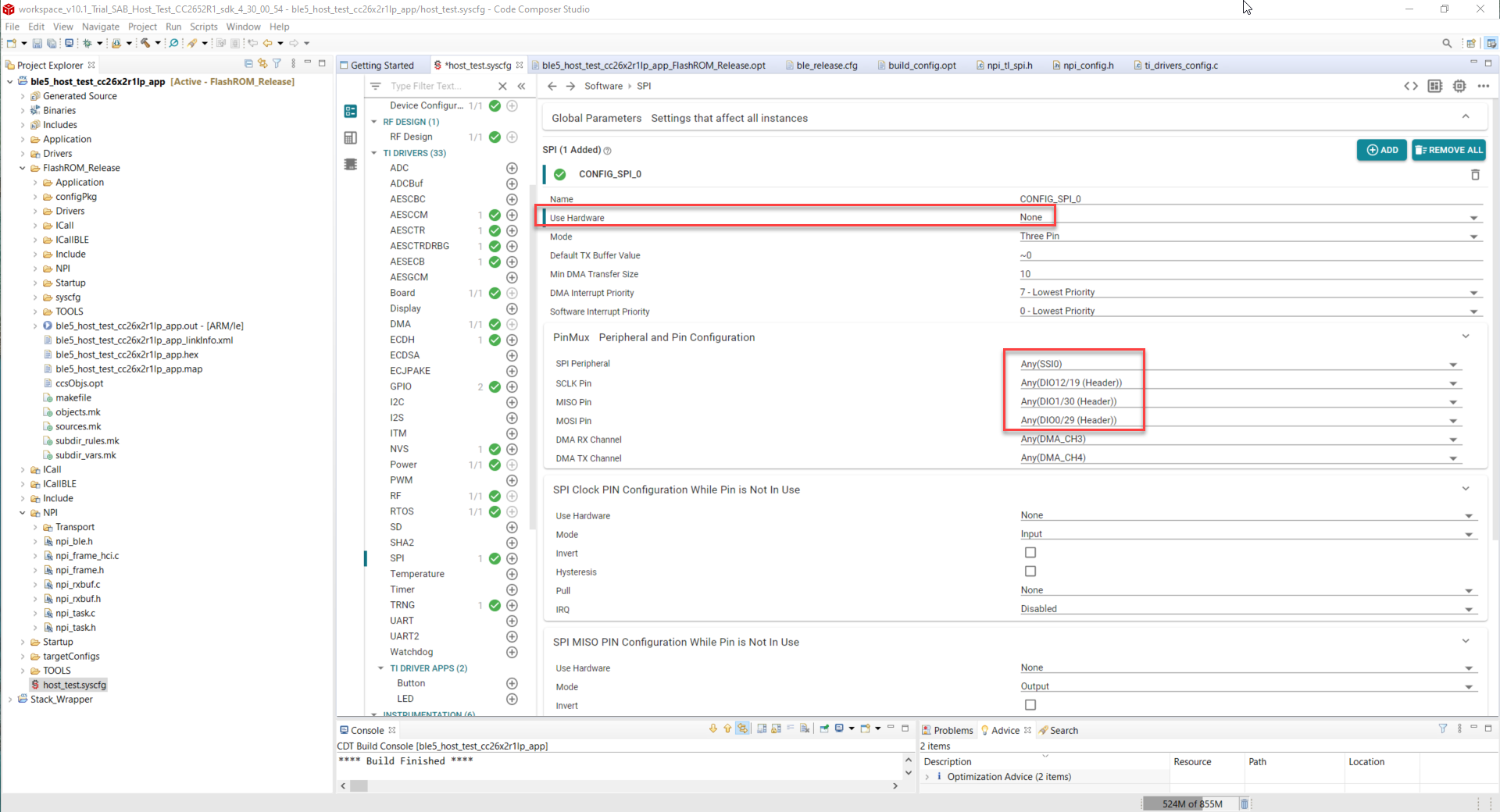
The only thing we need to change in the past (compared to launchpad) was the definition of SPI pins (I need to use SPI0 with CLK, MISO, MOSI, M2S and S2M). In rest everything was the same.

With the new host_test.syscfg I have not managed to do that because of multiple unclear settings. Besides compilation errors, I did not find out in sysconfig where to set the M2S and S2M only CLK MISO and MOSI.

What are the correct steps for what I am trying to do?

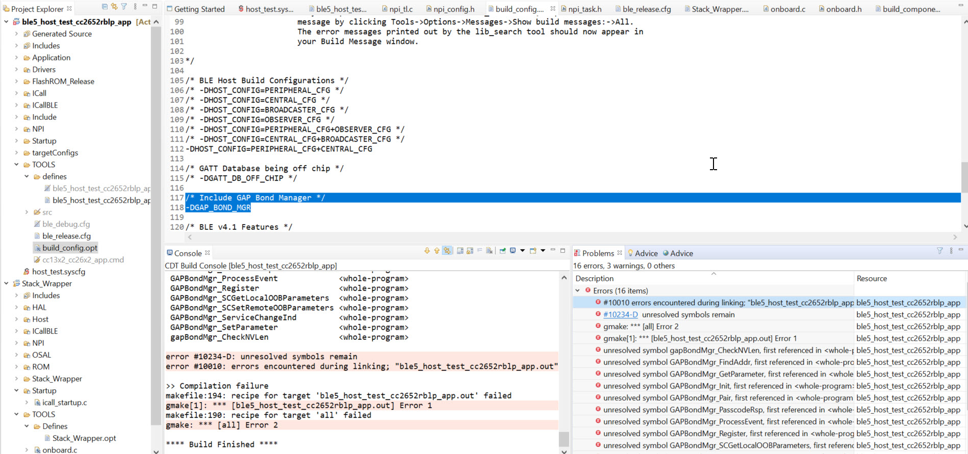
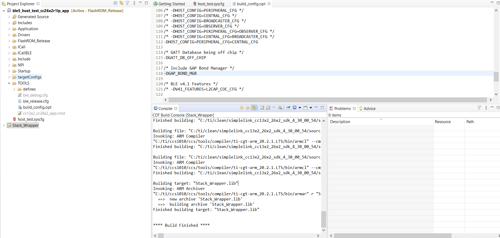
At the moment this is where I am stuck:

I import in CCS10.1.1 Host_test project from simplelink_cc13x2_26x2_sdk_4_30_00_54.

Compile ->OK

I select Use Custom Board File

Compile ->OK

I remove Display (UART is removed automatically as well) since we do not have a display

Compile failures:

#20 identifier "CONFIG_DISPLAY_UART" is undefined npi_tl_uart.c /ble5_host_test_cc26x2r1lp_app/NPI/Transport/UART line 163 C/C++ Problem

Alternatively: in the past there was the Board.h file that made use of my custom board file. Is it possible to easily use that board file in the host_test project that was created with host_test.syscfg?

  • krs,

    I will assign someone to assist you.

    -Luis

  • Hi Krs,

    Setting M2S and S2M:

    To clarify, did you configure M2S and S2M specifically in SysConfig for SPI previously with host_test or previous SDK? Are these used as master ready and slave ready pins? If so, these can be added within SysConfig as GPIOs. If this is not what you were looking for, can you please describe what M2S and S2M were used for in your project? Thanks!

    Compilation failure:

    I believe you are receiving the compilation failure because of the predefine symbol NPI_USE_UART. To undefine this, access either ble5_host_test_cc26x2r1lp_app_FlashROM_Debug.opt or ble5_host_test_cc26x2r1lp_app_FlashROM_Release.opt depending on which .opt file you are using. These can be found within the example folder host_test/tirtos/ccs/defines. Modify the following:

    - Change -DxNPI_USE_SPI to -DNPI_USE_SPI to use SPI for NPI

    - Change -DNPI_USE_UART to be -DxNPI_USE_UART to disable using UART for NPI. The compilation error is occurring due to NPI by default using UART instead of SPI. Within NPI, npi_tl.c is calling a function that then calls a function within npi_tl_uart.c which contains the define CONFIG_DISPLAY_UART.

    Best Regards,

    Jenny

  • First a big thank you for the detailed description! It clarified a few things for me.

    But the error remains. Here all the steps I do:

    I import in CCS10.1.1 Host_test project from simplelink_cc13x2_26x2_sdk_4_30_00_54.

    Compile ->OK

    I select Use Custom Board File

    Compile ->OK

    on HDD in example folder host_test/tirtos/ccs/defines I change in both release and debug .opt for NPI not to use UART but SPI

    now I have in that area...

    -DNPI_SPI_CONFIG=CONFIG_SPI_0
    -DNPI_USE_SPI
    -DxNPI_USE_UART
    -DxPOWER_SAVING

    Compile ->OK

    I remove Display (UART is removed automatically as well) since we do not have a display

    Compile fails with same error as before:

    #20 identifier "CONFIG_DISPLAY_UART" is undefined npi_tl_uart.c /ble5_host_test_cc26x2r1lp_app/NPI/Transport/UART line 163 C/C++ Problem

  • Hi Krs,

    Thanks for making the changes!

    If you are still receiving this error I suspect it's still because the NPI_USE_UART predefine symbol is still being used. This is because, npi_tl_uart.h is only pulled in if NPI_USE_UART is defined as seen in the following piece of code from npi_tl.c:

    #if defined(NPI_USE_SPI)
    #include "inc/npi_tl_spi.h"
    #elif defined(NPI_USE_UART)
    #include "inc/npi_tl_uart.h"
    #else
    #error Must define an underlying serial bus for NPI
    #endif

    I would suggest perform the steps in the following order:

    1. Verify in a text editor that both .opts are exactly like the changes you made and save.

    2. Create a new workspace and then import your project.

    3. Verify in npi_tl.c (located under NPI/Transport in your Project Explorer) line 71  that you see the #elif defined(NPI_USE_UART) is greyed out so that npi_tl_uart.h is not being used.

    Best Regards,

    Jenny

  • 1. Both .opts are the same.

    2. Created a new workspace and reimported a clean project

    3. npi_tl.c the NPI_USE_UART is greyed out (see pic)

    Error:

  • In the end I do not use UART so I just removed from Build the file npi_tl_uart.c, and got rid of the error above.

    Now I try to configure the SPI on my custom board.

    I have -DNPI_SPI_CONFIG=CONFIG_SPI_0

    As SPI I have... (As SPI Peripheral I can select only SSI0 - what does this setting do?)

    At GPIO I added Master Ready and Slave Ready like this.

    In npi_config.h i have:

    #if !defined(NPI_SPI_CONFIG)
    #define NPI_SPI_CONFIG CONFIG_SPI_0
    #endif
    
    #ifndef NPI_FLOW_CTRL
      #ifdef POWER_SAVING
        #define NPI_FLOW_CTRL       1
      #else
        #define NPI_FLOW_CTRL       0
      #endif
    #elif !(NPI_FLOW_CTRL == 0) && !(NPI_FLOW_CTRL == 1)
      #error "NPI ERROR: NPI_FLOW_CTRL can only be assigned 0 (disabled) or 1 (enabled)"
    #endif
    
    #if (NPI_FLOW_CTRL == 1)
    	#ifdef NPI_USE_SPI
    		//#if (NPI_SPI_CONFIG == Board_SPI1)
    			#define MRDY_PIN Board_SPI0_MRDY
    			#define SRDY_PIN Board_SPI0_SRDY
    		//#else
    		//	#error "NPI ERROR: Board_SPI1 SPI module must be used for NPI."
    		//#endif
    
    	#elif defined(NPI_USE_UART)
    		#define MRDY_PIN Board_PIN_BUTTON0
    		#define SRDY_PIN Board_PIN_BUTTON1
    	#endif
      #define SRDY_ENABLE()                   PIN_setOutputValue(hNpiHandshakePins, SRDY_PIN, 0) /* RTS low */
      #define SRDY_DISABLE()                  PIN_setOutputValue(hNpiHandshakePins, SRDY_PIN, 1) /* RTS high */
    #else
      #define SRDY_ENABLE()
      #define SRDY_DISABLE()
    #endif // NPI_FLOW_CTRL = 1

    Is this the correct way?

    Previous to sysconfig It was mandatory to use Board_SPI1, is this obsolete now?

    "

    The NPI uses the SPI module pointed by the symbol Board_SPI1 (this is configured in npi_config.h). You cannot easily change this.

    However, you can safely modify the pins used by each SPI. You can also change the definition of the symbol Board_SPI1 (in Board.h) to use the SPI module you want (CC2640R2_LAUNCHXL_SPI0 or CC2640R2_LAUNCHXL_SPI1).  In that case be sure to properly define all the pins required by the SPI chosen :)

    "

  • Hi Krs,

    I apologize for the delayed response.

    Yes you are correct. To use the MRDY_PIN and SRDY_PIN you need to replace your GPIO defines generated by SysConfig as you have already done. In addition, I believe you will need to define NPI_FLOW_CTRL as -DNPI_FLOW_CTR=1. 

    Can you open your host_test.syscfg file within a text editor and locate the SPI portion please? Does it state that the instance is SPI1 or SP0? I believe it is still using SPI1, regardless of the name. I will also contact the person from the thread you are referencing to confirm this.

    Best Regards,

    Jenny

  • The initial thread for using SPI0 is this

    And below my sysconfig file:

    /**
     * These arguments were used when this file was generated. They will be automatically applied on subsequent loads
     * via the GUI or CLI. Run CLI with '--help' for additional information on how to override these arguments.
     * @cliArgs --device "CC2652R1FRGZ" --package "RGZ" --part "Default" --product "simplelink_cc13x2_26x2_sdk@4.30.00.54"
     * @versions {"data":"2020090214","timestamp":"2020090214","tool":"1.6.0+1543","templates":"2020090214"}
     */
    /**
     * Import the modules used in this configuration.
     */
    const CCFG        = scripting.addModule("/ti/devices/CCFG");
    const custom      = scripting.addModule("/ti/devices/radioconfig/custom");
    const rfdesign    = scripting.addModule("/ti/devices/radioconfig/rfdesign");
    const AESCCM      = scripting.addModule("/ti/drivers/AESCCM");
    const AESCCM1     = AESCCM.addInstance();
    const AESCTRDRBG  = scripting.addModule("/ti/drivers/AESCTRDRBG");
    const AESCTRDRBG1 = AESCTRDRBG.addInstance();
    const AESECB      = scripting.addModule("/ti/drivers/AESECB");
    const AESECB1     = AESECB.addInstance();
    const ECDH        = scripting.addModule("/ti/drivers/ECDH");
    const ECDH1       = ECDH.addInstance();
    const GPIO        = scripting.addModule("/ti/drivers/GPIO");
    const GPIO1       = GPIO.addInstance();
    const GPIO2       = GPIO.addInstance();
    const NVS         = scripting.addModule("/ti/drivers/NVS");
    const NVS1        = NVS.addInstance();
    const Power       = scripting.addModule("/ti/drivers/Power");
    const RF          = scripting.addModule("/ti/drivers/RF");
    const RTOS        = scripting.addModule("/ti/drivers/RTOS");
    const SPI         = scripting.addModule("/ti/drivers/SPI");
    const SPI1        = SPI.addInstance();
    const TRNG        = scripting.addModule("/ti/drivers/TRNG");
    const TRNG1       = TRNG.addInstance();
    /**
     * Write custom configuration values to the imported modules.
     */
    CCFG.enableCodeGeneration = false;
    CCFG.ccfgTemplate.$name   = "ti_devices_CCFGTemplateInit0";
    custom.ble                                                    = ["bt5le1m"];
    custom.radioConfigbt5le1m.$name                               = "ti_devices_radioconfig_settings_ble0";
    custom.radioConfigbt5le1m.paramVisibility                     = false;
    custom.radioConfigbt5le1m.codeExportConfig.$name              = "ti_devices_radioconfig_code_export_param0";
    custom.radioConfigbt5le1m.codeExportConfig.symGenMethod       = "Custom";
    custom.radioConfigbt5le1m.codeExportConfig.rfMode             = "RF_modeBle";
    custom.radioConfigbt5le1m.codeExportConfig.txPower            = "RF_BLE_txPowerTable";
    custom.radioConfigbt5le1m.codeExportConfig.txPowerSize        = "RF_BLE_TX_POWER_TABLE_SIZE";
    custom.radioConfigbt5le1m.codeExportConfig.overrides          = "pOverrides_ble";
    custom.radioConfigbt5le1m.codeExportConfig.stackOverride      = "ti/ble5stack/icall/inc/ble_overrides.h";
    custom.radioConfigbt5le1m.codeExportConfig.stackOverrideMacro = "BLE_STACK_OVERRIDES";
    custom.radioConfigbt5le1m.codeExportConfig.cmdList_ble        = [];
    AESCCM1.$name = "CONFIG_AESCCM0";
    AESCTRDRBG1.$name              = "CONFIG_AESCTRDRBG_0";
    AESCTRDRBG1.aesctrObject.$name = "CONFIG_AESCTR_0";
    AESECB1.$name = "CONFIG_AESECB0";
    ECDH1.$name = "CONFIG_ECDH0";
    GPIO1.pull              = "Pull Up";
    GPIO1.interruptTrigger  = "Falling Edge";
    GPIO1.mode              = "Dynamic";
    GPIO1.$name             = "Board_SPI0_MRDY";
    GPIO1.gpioPin.$assign   = "DIO_11";
    GPIO1.pinInstance.$name = "CONFIG_PIN_BTN1";
    GPIO2.pull              = "Pull Up";
    GPIO2.interruptTrigger  = "Falling Edge";
    GPIO2.mode              = "Dynamic";
    GPIO2.$name             = "Board_SPI0_SRDY";
    GPIO2.gpioPin.$assign   = "DIO_22";
    GPIO2.pinInstance.$name = "CONFIG_PIN_BTN2";
    NVS1.$name                    = "CONFIG_NVSINTERNAL";
    NVS1.internalFlash.$name      = "ti_drivers_nvs_NVSCC26XX0";
    NVS1.internalFlash.regionBase = 0x48000;
    NVS1.internalFlash.regionSize = 0x4000;
    SPI1.$name                    = "CONFIG_SPI_0";
    SPI1.spi.$assign              = "SSI0";
    SPI1.spi.sclkPin.$assign      = "DIO_9";
    SPI1.spi.misoPin.$assign      = "DIO_10";
    SPI1.spi.mosiPin.$assign      = "DIO_8";
    SPI1.spi.dmaRxChannel.$assign = "DMA_CH3";
    SPI1.spi.dmaTxChannel.$assign = "DMA_CH4";
    SPI1.sclkPinInstance.$name    = "CONFIG_PIN_0";
    SPI1.misoPinInstance.$name    = "CONFIG_PIN_1";
    SPI1.mosiPinInstance.$name    = "CONFIG_PIN_2";
    TRNG1.$name = "CONFIG_TRNG_0";
  • Regarding defining NPI_FLOW_CTRL as -DNPI_FLOW_CTR=1.

    is this not done in npi_config.h by defining DPOWER_SAVING in project.opt?

    #ifndef NPI_FLOW_CTRL
      #ifdef POWER_SAVING
        #define NPI_FLOW_CTRL       1
      #else
        #define NPI_FLOW_CTRL       0
      #endif
    #elif !(NPI_FLOW_CTRL == 0) && !(NPI_FLOW_CTRL == 1)
      #error "NPI ERROR: NPI_FLOW_CTRL can only be assigned 0 (disabled) or 1 (enabled)"
    #endif

  • Hi Krs,

    I apologize I had a typo in the previous post. It should be -DNPI_FLOW_CTRL=1 instead of -DNPI_FLOW_CTR=1.

    Yes, you you are correct, defining POWER_SAVING is sufficient in defining NPI_FLOW_CTRL to be 1.

    I have also verified with Clement from the other thread you referenced, the other thread was for the CC2640R2F which there is a restriction on which SPI peripheral you can use for NPI. However, with the CC26x2R1, there should not be any restriction, therefore you can use either SPI1 or SPI0. In the .opt file, by default the name "CONFIG_SPI_0" is used, however, as long as you choose a SPI and name the instance the same name "CONFIG_SPI_0", it should be fine.

    Best Regards,

    Jenny

  • ok.... I still do not have SPI working (but I can check some things on Monday)

    but now a new issue! when I enable in build_config.opt

    /* Include GAP Bond Manager */
    -DGAP_BOND_MGR

    I get a lot of linker errors.

    (This is for a CC2652RB project, but in rest all things are the same)

  • Hi Krs,

    This linker error is due to the linker not being able to find the definition of these functions which I believe are located in gapbondmgr.c.

    It appears that my default build_config.opt appears different from yours. Regardless, I added the define -DGAP_BOND_MGR as seen in the image below and it builds without the linking errors present in your project.

    Can you please provide me with both your host_test.syscfg file and build_config.opt file please? I can drop both in my workspace and attempt to build.

    I had some additional questions:

    - I do see that you said this is for a CC2652RB project, but the rest are the same. I wanted to clarify, is this just referring to the modifications detailed in the previous posts on this thread?

    - To verify, the projectspec is also unmodified correct?

    Best Regards,

    Jenny

  • I mixed up the topics a little it seems... CC2642R1 compiles just fine!! The problem appears only on CC2652RB. I will open a new topic for that. https://e2e.ti.com/support/wireless-connectivity/bluetooth/f/538/t/969836

    Open issue remains the SPI not working. Can you please take a look on my host_test.sysconfig file to see if everything looks in order?

    /**
     * These arguments were used when this file was generated. They will be automatically applied on subsequent loads
     * via the GUI or CLI. Run CLI with '--help' for additional information on how to override these arguments.
     * @cliArgs --device "CC2652R1FRGZ" --package "RGZ" --part "Default" --product "simplelink_cc13x2_26x2_sdk@4.30.00.54"
     * @versions {"data":"2020090214","timestamp":"2020090214","tool":"1.6.0+1543","templates":"2020090214"}
     */
    
    /**
     * Import the modules used in this configuration.
     */
    const CCFG        = scripting.addModule("/ti/devices/CCFG");
    const custom      = scripting.addModule("/ti/devices/radioconfig/custom");
    const rfdesign    = scripting.addModule("/ti/devices/radioconfig/rfdesign");
    const AESCCM      = scripting.addModule("/ti/drivers/AESCCM");
    const AESCCM1     = AESCCM.addInstance();
    const AESCTRDRBG  = scripting.addModule("/ti/drivers/AESCTRDRBG");
    const AESCTRDRBG1 = AESCTRDRBG.addInstance();
    const AESECB      = scripting.addModule("/ti/drivers/AESECB");
    const AESECB1     = AESECB.addInstance();
    const ECDH        = scripting.addModule("/ti/drivers/ECDH");
    const ECDH1       = ECDH.addInstance();
    const GPIO        = scripting.addModule("/ti/drivers/GPIO");
    const GPIO1       = GPIO.addInstance();
    const GPIO2       = GPIO.addInstance();
    const NVS         = scripting.addModule("/ti/drivers/NVS");
    const NVS1        = NVS.addInstance();
    const Power       = scripting.addModule("/ti/drivers/Power");
    const RF          = scripting.addModule("/ti/drivers/RF");
    const RTOS        = scripting.addModule("/ti/drivers/RTOS");
    const SPI         = scripting.addModule("/ti/drivers/SPI");
    const SPI1        = SPI.addInstance();
    const TRNG        = scripting.addModule("/ti/drivers/TRNG");
    const TRNG1       = TRNG.addInstance();
    
    /**
     * Write custom configuration values to the imported modules.
     */
    CCFG.enableCodeGeneration = false;
    CCFG.ccfgTemplate.$name   = "ti_devices_CCFGTemplateInit0";
    
    custom.ble                                                    = ["bt5le1m"];
    custom.radioConfigbt5le1m.$name                               = "ti_devices_radioconfig_settings_ble0";
    custom.radioConfigbt5le1m.paramVisibility                     = false;
    custom.radioConfigbt5le1m.codeExportConfig.$name              = "ti_devices_radioconfig_code_export_param0";
    custom.radioConfigbt5le1m.codeExportConfig.symGenMethod       = "Custom";
    custom.radioConfigbt5le1m.codeExportConfig.rfMode             = "RF_modeBle";
    custom.radioConfigbt5le1m.codeExportConfig.txPower            = "RF_BLE_txPowerTable";
    custom.radioConfigbt5le1m.codeExportConfig.txPowerSize        = "RF_BLE_TX_POWER_TABLE_SIZE";
    custom.radioConfigbt5le1m.codeExportConfig.overrides          = "pOverrides_ble";
    custom.radioConfigbt5le1m.codeExportConfig.stackOverride      = "ti/ble5stack/icall/inc/ble_overrides.h";
    custom.radioConfigbt5le1m.codeExportConfig.stackOverrideMacro = "BLE_STACK_OVERRIDES";
    custom.radioConfigbt5le1m.codeExportConfig.cmdList_ble        = [];
    
    AESCCM1.$name = "CONFIG_AESCCM0";
    
    AESCTRDRBG1.$name              = "CONFIG_AESCTRDRBG_0";
    AESCTRDRBG1.aesctrObject.$name = "CONFIG_AESCTR_0";
    
    AESECB1.$name = "CONFIG_AESECB0";
    
    ECDH1.$name = "CONFIG_ECDH0";
    
    GPIO1.pull              = "Pull Up";
    GPIO1.$name             = "Board_SPI0_MRDY";
    GPIO1.interruptTrigger  = "Both Edges";
    GPIO1.gpioPin.$assign   = "DIO_11";
    GPIO1.pinInstance.$name = "CONFIG_PIN_BTN1";
    
    GPIO2.pull              = "Pull Up";
    GPIO2.$name             = "Board_SPI0_SRDY";
    GPIO2.mode              = "Output";
    GPIO2.gpioPin.$assign   = "DIO_22";
    GPIO2.pinInstance.$name = "CONFIG_PIN_BTN2";
    
    NVS1.$name                    = "CONFIG_NVSINTERNAL";
    NVS1.internalFlash.$name      = "ti_drivers_nvs_NVSCC26XX0";
    NVS1.internalFlash.regionBase = 0x48000;
    NVS1.internalFlash.regionSize = 0x4000;
    
    SPI1.$name                       = "CONFIG_SPI_0";
    SPI1.spi.$assign                 = "SSI0";
    SPI1.spi.sclkPin.$assign         = "DIO_9";
    SPI1.spi.misoPin.$assign         = "DIO_10";
    SPI1.spi.mosiPin.$assign         = "DIO_8";
    SPI1.spi.dmaRxChannel.$assign    = "DMA_CH3";
    SPI1.spi.dmaTxChannel.$assign    = "DMA_CH4";
    SPI1.sclkPinInstance.$name       = "CONFIG_PIN_0";
    SPI1.sclkPinInstance.mode        = "Input";
    SPI1.sclkPinInstance.pull        = "Pull Down";
    SPI1.misoPinInstance.$name       = "CONFIG_PIN_1";
    SPI1.misoPinInstance.outputState = "High";
    SPI1.misoPinInstance.pull        = "Pull Down";
    SPI1.misoPinInstance.mode        = "Output";
    SPI1.mosiPinInstance.$name       = "CONFIG_PIN_2";
    SPI1.mosiPinInstance.mode        = "Input";
    SPI1.mosiPinInstance.pull        = "Pull Down";
    
    TRNG1.$name = "CONFIG_TRNG_0";
    

  • Hi Krs,

    Thanks for the clarification on the CC2652RB issue and splitting the thread. After taking a look at the host_test.syscfg you posted, it appears to be correct and nothing noticeably wrong stands out to me. Due to this let's try a few different methods of trying to debug this issue:

    1. Are you able to switch the SPI peripheral to SSI1 to try the SPI1 peripheral? This is a test to verify that this is not a SPI peripheral issue.

    2. Can you also share the generated SysConfig files located under Generated Source please? I want to verify the pin defines look correct.

    3. Another thing you can do is possibly verifying in an example project (such as one repurposed from the spimaster/spislave TI driver example projects) that the SPI driver itself is working properly and that the pin connections are correct. In addition, if you have a logic analyzer, can you verify that you can see bits being transmitted over the MOSI line/MRDY and SRDY line are correctly being pulled low/the SCLK line is clocking properly?

    I would also suggest maybe removing the MRDY and SRDY lines (along with the POWER_SAVE define for the NPI_FLOW_CTRL define enabled code) to remove complexity in the code and verify that you can see communication occurring with just 3 pin (SCLK, MISO, and MOSI).

    4. Diving a little deeper, there is a callback within npi_tl_spi.c called NPITLSPI_Callback that should be invoked upon transmission completion. Can you place a breakpoint within this function to see if it hits?

    Best Regards,

    Jenny

  • Let me replay with a general remark and if this is not helping I will address al your questions in order.

    Not 100% positive but no matter what I select as pin for SPI CLK, a clk is generated on default SPI0 CLK pin ... DIO10 !!

    These are the custom pins I try to set with clk on DIO9.

    These are he default pins for SPI 0 with  clock on DIO 10

    Below the generated Source/ti_driver_config.h and .c

    /*
     *  ======== ti_drivers_config.h ========
     *  Configured TI-Drivers module declarations
     *
     *  The macros defines herein are intended for use by applications which
     *  directly include this header. These macros should NOT be hard coded or
     *  copied into library source code.
     *
     *  Symbols declared as const are intended for use with libraries.
     *  Library source code must extern the correct symbol--which is resolved
     *  when the application is linked.
     *
     *  DO NOT EDIT - This file is generated for the CC2652RB_LAUNCHXL
     *  by the SysConfig tool.
     */
    #ifndef ti_drivers_config_h
    #define ti_drivers_config_h
    
    #define CONFIG_SYSCONFIG_PREVIEW
    
    #define CONFIG_CC2652RB_LAUNCHXL
    #ifndef DeviceFamily_CC26X2
    #define DeviceFamily_CC26X2
    #endif
    
    #include <ti/devices/DeviceFamily.h>
    
    #include <stdint.h>
    
    /* support C++ sources */
    #ifdef __cplusplus
    extern "C" {
    #endif
    
    
    /*
     *  ======== CCFG ========
     */
    #include DeviceFamily_constructPath(driverlib/osc.h)
    
    
    /*
     *  ======== AESCCM ========
     */
    
    extern const uint_least8_t                  CONFIG_AESCCM0_CONST;
    #define CONFIG_AESCCM0                      0
    #define CONFIG_TI_DRIVERS_AESCCM_COUNT      1
    
    
    /*
     *  ======== AESCTR ========
     */
    
    extern const uint_least8_t                  CONFIG_AESCTR_0_CONST;
    #define CONFIG_AESCTR_0                     0
    #define CONFIG_TI_DRIVERS_AESCTR_COUNT      1
    
    
    /*
     *  ======== AESCTRDRBG ========
     */
    
    extern const uint_least8_t                      CONFIG_AESCTRDRBG_0_CONST;
    #define CONFIG_AESCTRDRBG_0                     0
    #define CONFIG_TI_DRIVERS_AESCTRDRBG_COUNT      1
    
    
    /*
     *  ======== AESECB ========
     */
    
    extern const uint_least8_t                  CONFIG_AESECB0_CONST;
    #define CONFIG_AESECB0                      0
    #define CONFIG_TI_DRIVERS_AESECB_COUNT      1
    
    
    /*
     *  ======== ECDH ========
     */
    
    extern const uint_least8_t              CONFIG_ECDH0_CONST;
    #define CONFIG_ECDH0                    0
    #define CONFIG_TI_DRIVERS_ECDH_COUNT    1
    
    
    /*
     *  ======== GPIO ========
     */
    
    /* DIO11 */
    extern const uint_least8_t              Board_SPI0_MRDY_CONST;
    #define Board_SPI0_MRDY                 0
    /* DIO22 */
    extern const uint_least8_t              Board_SPI0_SRDY_CONST;
    #define Board_SPI0_SRDY                 1
    #define CONFIG_TI_DRIVERS_GPIO_COUNT    2
    
    /* LEDs are active high */
    #define CONFIG_GPIO_LED_ON  (1)
    #define CONFIG_GPIO_LED_OFF (0)
    
    #define CONFIG_LED_ON  (CONFIG_GPIO_LED_ON)
    #define CONFIG_LED_OFF (CONFIG_GPIO_LED_OFF)
    
    
    /*
     *  ======== NVS ========
     */
    
    extern const uint_least8_t              CONFIG_NVSINTERNAL_CONST;
    #define CONFIG_NVSINTERNAL              0
    #define CONFIG_TI_DRIVERS_NVS_COUNT     1
    
    
    /*
     *  ======== PIN ========
     */
    #include <ti/drivers/PIN.h>
    
    extern const PIN_Config BoardGpioInitTable[];
    
    /* Parent Signal: Board_SPI0_MRDY GPIO Pin, (DIO11) */
    #define CONFIG_PIN_BTN1                   0x0000000b
    /* Parent Signal: Board_SPI0_SRDY GPIO Pin, (DIO22) */
    #define CONFIG_PIN_BTN2                   0x00000016
    /* Parent Signal: CONFIG_SPI_0 SCLK, (DIO9) */
    #define CONFIG_PIN_0                   0x00000009
    /* Parent Signal: CONFIG_SPI_0 MISO, (DIO10) */
    #define CONFIG_PIN_1                   0x0000000a
    /* Parent Signal: CONFIG_SPI_0 MOSI, (DIO8) */
    #define CONFIG_PIN_2                   0x00000008
    #define CONFIG_TI_DRIVERS_PIN_COUNT    5


    /*
     *  ======== SPI ========
     */
    
    /*
     *  MOSI: DIO8
     *  MISO: DIO10
     *  SCLK: DIO9
     */
    extern const uint_least8_t              CONFIG_SPI_0_CONST;
    #define CONFIG_SPI_0                    0
    #define CONFIG_TI_DRIVERS_SPI_COUNT     1
    
    
    /*
     *  ======== TRNG ========
     */
    
    extern const uint_least8_t              CONFIG_TRNG_0_CONST;
    #define CONFIG_TRNG_0                   0
    #define CONFIG_TI_DRIVERS_TRNG_COUNT    1
    
    
    /*
     *  ======== Board_init ========
     *  Perform all required TI-Drivers initialization
     *
     *  This function should be called once at a point before any use of
     *  TI-Drivers.
     */
    extern void Board_init(void);
    
    /*
     *  ======== Board_initGeneral ========
     *  (deprecated)
     *
     *  Board_initGeneral() is defined purely for backward compatibility.
     *
     *  All new code should use Board_init() to do any required TI-Drivers
     *  initialization _and_ use <Driver>_init() for only where specific drivers
     *  are explicitly referenced by the application.  <Driver>_init() functions
     *  are idempotent.
     */
    #define Board_initGeneral Board_init
    
    #ifdef __cplusplus
    }
    #endif
    
    #endif /* include guard */
    

    /*
     *  ======== ti_drivers_config.c ========
     *  Configured TI-Drivers module definitions
     *
     *  DO NOT EDIT - This file is generated for the CC2652RB_LAUNCHXL
     *  by the SysConfig tool.
     */
    
    #include <stddef.h>
    #include <stdint.h>
    
    #ifndef DeviceFamily_CC26X2
    #define DeviceFamily_CC26X2
    #endif
    
    #include <ti/devices/DeviceFamily.h>
    
    #include "ti_drivers_config.h"
    
    /*
     *  =============================== AESCCM ===============================
     */
    
    #include <ti/drivers/AESCCM.h>
    #include <ti/drivers/aesccm/AESCCMCC26XX.h>
    
    #define CONFIG_AESCCM_COUNT 1
    AESCCMCC26XX_Object aesccmCC26XXObjects[CONFIG_AESCCM_COUNT];
    
    /*
     *  ======== aesccmCC26XXHWAttrs ========
     */
    const AESCCMCC26XX_HWAttrs aesccmCC26XXHWAttrs[CONFIG_AESCCM_COUNT] = {
        {
            .intPriority = (~0),
        },
    };
    
    const AESCCM_Config AESCCM_config[CONFIG_AESCCM_COUNT] = {
        {   /* CONFIG_AESCCM0 */
            .object  = &aesccmCC26XXObjects[CONFIG_AESCCM0],
            .hwAttrs = &aesccmCC26XXHWAttrs[CONFIG_AESCCM0]
        },
    };
    
    const uint_least8_t CONFIG_AESCCM0_CONST = CONFIG_AESCCM0;
    const uint_least8_t AESCCM_count = CONFIG_AESCCM_COUNT;
    
    /*
     *  =============================== AESCTR ===============================
     */
    
    #include <ti/drivers/AESCTR.h>
    #include <ti/drivers/aesctr/AESCTRCC26XX.h>
    
    #define CONFIG_AESCTR_COUNT 1
    AESCTRCC26XX_Object aesctrCC26XXObjects[CONFIG_AESCTR_COUNT];
    
    /*
     *  ======== aesctrCC26XXHWAttrs ========
     */
    const AESCTRCC26XX_HWAttrs aesctrCC26XXHWAttrs[CONFIG_AESCTR_COUNT] = {
        {
            .intPriority = (~0),
        },
    };
    
    const AESCTR_Config AESCTR_config[CONFIG_AESCTR_COUNT] = {
        {   /* CONFIG_AESCTR_0 */
            .object  = &aesctrCC26XXObjects[CONFIG_AESCTR_0],
            .hwAttrs = &aesctrCC26XXHWAttrs[CONFIG_AESCTR_0]
        },
    };
    
    const uint_least8_t CONFIG_AESCTR_0_CONST = CONFIG_AESCTR_0;
    const uint_least8_t AESCTR_count = CONFIG_AESCTR_COUNT;
    
    /*
     *  =============================== AESCTRDRBG ===============================
     */
    
    #include <ti/drivers/AESCTRDRBG.h>
    #include <ti/drivers/aesctrdrbg/AESCTRDRBGXX.h>
    
    #define CONFIG_AESCTRDRBG_COUNT 1
    
    /*
     *  ======== aesctrdrbgXXObjects ========
     */
    AESCTRDRBGXX_Object aesctrdrbgXXObjects[CONFIG_AESCTRDRBG_COUNT];
    
    /*
     *  ======== aesctrdrbgXXHWAttrs ========
     */
    const AESCTRDRBGXX_HWAttrs aesctrdrbgXXHWAttrs[CONFIG_AESCTRDRBG_COUNT] = {
        /* CONFIG_AESCTRDRBG_0 */
        {
            .aesctrIndex = CONFIG_AESCTR_0
        },
    };
    
    /*
     *  ======== AESCTRDRBG_config ========
     */
    const AESCTRDRBG_Config AESCTRDRBG_config[CONFIG_AESCTRDRBG_COUNT] = {
        /* CONFIG_AESCTRDRBG_0 */
        {
            .object = &aesctrdrbgXXObjects[CONFIG_AESCTRDRBG_0],
            .hwAttrs = &aesctrdrbgXXHWAttrs[CONFIG_AESCTRDRBG_0]
        },
    };
    
    const uint_least8_t CONFIG_AESCTRDRBG_0_CONST = CONFIG_AESCTRDRBG_0;
    const uint_least8_t AESCTRDRBG_count = CONFIG_AESCTRDRBG_COUNT;
    
    /*
     *  =============================== AESECB ===============================
     */
    
    #include <ti/drivers/AESECB.h>
    #include <ti/drivers/aesecb/AESECBCC26XX.h>
    
    #define CONFIG_AESECB_COUNT 1
    AESECBCC26XX_Object aesecbCC26XXObjects[CONFIG_AESECB_COUNT];
    
    /*
     *  ======== aesecbCC26XXHWAttrs ========
     */
    const AESECBCC26XX_HWAttrs aesecbCC26XXHWAttrs[CONFIG_AESECB_COUNT] = {
        {
            .intPriority = (~0),
        },
    };
    
    const AESECB_Config AESECB_config[CONFIG_AESECB_COUNT] = {
        {   /* CONFIG_AESECB0 */
            .object  = &aesecbCC26XXObjects[CONFIG_AESECB0],
            .hwAttrs = &aesecbCC26XXHWAttrs[CONFIG_AESECB0]
        },
    };
    
    
    const uint_least8_t CONFIG_AESECB0_CONST = CONFIG_AESECB0;
    const uint_least8_t AESECB_count = CONFIG_AESECB_COUNT;
    
    /*
     *  =============================== DMA ===============================
     */
    
    #include <ti/drivers/dma/UDMACC26XX.h>
    #include <ti/devices/cc13x2_cc26x2/driverlib/udma.h>
    #include <ti/devices/cc13x2_cc26x2/inc/hw_memmap.h>
    
    UDMACC26XX_Object udmaCC26XXObject;
    
    const UDMACC26XX_HWAttrs udmaCC26XXHWAttrs = {
        .baseAddr        = UDMA0_BASE,
        .powerMngrId     = PowerCC26XX_PERIPH_UDMA,
        .intNum          = INT_DMA_ERR,
        .intPriority     = (~0)
    };
    
    const UDMACC26XX_Config UDMACC26XX_config[1] = {
        {
            .object         = &udmaCC26XXObject,
            .hwAttrs        = &udmaCC26XXHWAttrs,
        },
    };
    
    /*
     *  =============================== ECDH ===============================
     */
    
    #include <ti/drivers/ECDH.h>
    #include <ti/drivers/ecdh/ECDHCC26X2.h>
    
    #define CONFIG_ECDH_COUNT 1
    
    ECDHCC26X2_Object ecdhCC26X2Objects[CONFIG_ECDH_COUNT];
    
    /*
     *  ======== ecdhCC26X2HWAttrs ========
     */
    const ECDHCC26X2_HWAttrs ecdhCC26X2HWAttrs[CONFIG_ECDH_COUNT] = {
        {
            .intPriority = (~0),
        },
    };
    
    const ECDH_Config ECDH_config[CONFIG_ECDH_COUNT] = {
        {   /* CONFIG_ECDH0 */
            .object         = &ecdhCC26X2Objects[CONFIG_ECDH0],
            .hwAttrs        = &ecdhCC26X2HWAttrs[CONFIG_ECDH0]
        },
    };
    
    const uint_least8_t CONFIG_ECDH0_CONST = CONFIG_ECDH0;
    const uint_least8_t ECDH_count = CONFIG_ECDH_COUNT;
    
    /*
     *  =============================== GPIO ===============================
     */
    
    #include <ti/drivers/GPIO.h>
    #include <ti/drivers/gpio/GPIOCC26XX.h>
    
    #define CONFIG_GPIO_COUNT 2
    
    /*
     *  ======== gpioPinConfigs ========
     *  Array of Pin configurations
     */
    GPIO_PinConfig gpioPinConfigs[] = {
        /* Board_SPI0_MRDY */
        GPIOCC26XX_DIO_11 | GPIO_CFG_IN_PU | GPIO_CFG_IN_INT_BOTH_EDGES,
        /* Board_SPI0_SRDY */
        GPIOCC26XX_DIO_22 | GPIO_CFG_OUT_STD | GPIO_CFG_OUT_STR_MED | GPIO_CFG_OUT_HIGH,
    };
    
    /*
     *  ======== gpioCallbackFunctions ========
     *  Array of callback function pointers
     *
     *  NOTE: Unused callback entries can be omitted from the callbacks array to
     *  reduce memory usage by enabling callback table optimization
     *  (GPIO.optimizeCallbackTableSize = true)
     */
    GPIO_CallbackFxn gpioCallbackFunctions[] = {
        /* Board_SPI0_MRDY */
        NULL,
        /* Board_SPI0_SRDY */
        NULL,
    };
    
    const uint_least8_t Board_SPI0_MRDY_CONST = Board_SPI0_MRDY;
    const uint_least8_t Board_SPI0_SRDY_CONST = Board_SPI0_SRDY;
    
    /*
     *  ======== GPIOCC26XX_config ========
     */
    const GPIOCC26XX_Config GPIOCC26XX_config = {
        .pinConfigs = (GPIO_PinConfig *)gpioPinConfigs,
        .callbacks = (GPIO_CallbackFxn *)gpioCallbackFunctions,
        .numberOfPinConfigs = 2,
        .numberOfCallbacks = 2,
        .intPriority = (~0)
    };
    
    /*
     *  =============================== NVS ===============================
     */
    
    #include <ti/drivers/NVS.h>
    #include <ti/drivers/nvs/NVSCC26XX.h>
    
    /*
     *  NVSCC26XX Internal NVS flash region definitions
     *
     * Place uninitialized char arrays at addresses
     * corresponding to the 'regionBase' addresses defined in
     * the configured NVS regions. These arrays are used as
     * place holders so that the linker will not place other
     * content there.
     *
     * For GCC targets, the char arrays are each placed into
     * the shared ".nvs" section. The user must add content to
     * their GCC linker command file to place the .nvs section
     * at the lowest 'regionBase' address specified in their NVS
     * regions.
     */
    
    #if defined(__TI_COMPILER_VERSION__) || defined(__clang__)
    
    static char flashBuf0[0x4000] __attribute__ ((retain, noinit, location(0x48000)));
    
    #elif defined(__IAR_SYSTEMS_ICC__)
    
    __no_init static char flashBuf0[0x4000] @ 0x48000;
    
    #elif defined(__GNUC__)
    
    __attribute__ ((section (".nvs")))
    static char flashBuf0[0x4000];
    
    #endif
    
    NVSCC26XX_Object nvsCC26XXObjects[1];
    
    static const NVSCC26XX_HWAttrs nvsCC26XXHWAttrs[1] = {
        /* CONFIG_NVSINTERNAL */
        {
            .regionBase = (void *) flashBuf0,
            .regionSize = 0x4000
        },
    };
    
    #define CONFIG_NVS_COUNT 1
    
    const NVS_Config NVS_config[CONFIG_NVS_COUNT] = {
        /* CONFIG_NVSINTERNAL */
        {
            .fxnTablePtr = &NVSCC26XX_fxnTable,
            .object = &nvsCC26XXObjects[0],
            .hwAttrs = &nvsCC26XXHWAttrs[0],
        },
    };
    
    const uint_least8_t CONFIG_NVSINTERNAL_CONST = CONFIG_NVSINTERNAL;
    const uint_least8_t NVS_count = CONFIG_NVS_COUNT;
    
    /*
     *  =============================== PIN ===============================
     */
    #include <ti/drivers/PIN.h>
    #include <ti/drivers/pin/PINCC26XX.h>
    
    #define CONFIG_PIN_COUNT 5
    
    const PIN_Config BoardGpioInitTable[CONFIG_PIN_COUNT + 1] = {
        /* Parent Signal: Board_SPI0_MRDY GPIO Pin, (DIO11) */
        CONFIG_PIN_BTN1 | PIN_INPUT_EN | PIN_PULLUP | PIN_IRQ_DIS,
        /* Parent Signal: Board_SPI0_SRDY GPIO Pin, (DIO22) */
        CONFIG_PIN_BTN2 | PIN_GPIO_OUTPUT_EN | PIN_GPIO_HIGH | PIN_PUSHPULL | PIN_DRVSTR_MED,
        /* Parent Signal: CONFIG_SPI_0 SCLK, (DIO9) */
        CONFIG_PIN_0 | PIN_INPUT_EN | PIN_PULLDOWN | PIN_IRQ_DIS,
        /* Parent Signal: CONFIG_SPI_0 MISO, (DIO10) */
        CONFIG_PIN_1 | PIN_GPIO_OUTPUT_EN | PIN_GPIO_HIGH | PIN_PUSHPULL | PIN_DRVSTR_MED,
        /* Parent Signal: CONFIG_SPI_0 MOSI, (DIO8) */
        CONFIG_PIN_2 | PIN_INPUT_EN | PIN_NOPULL | PIN_IRQ_DIS,
    
        PIN_TERMINATE
    };
    
    const PINCC26XX_HWAttrs PINCC26XX_hwAttrs = {
        .intPriority = (~0),
        .swiPriority = 0
    };
    
    /*
     *  =============================== Power ===============================
     */
    #include <ti/drivers/Power.h>
    #include <ti/drivers/power/PowerCC26X2.h>
    #include "ti_drivers_config.h"
    
    extern void PowerCC26XX_standbyPolicy(void);
    extern bool PowerCC26XX_calibrate(unsigned int);
    
    const PowerCC26X2_Config PowerCC26X2_config = {
        .enablePolicy             = true,
        .policyInitFxn            = NULL,
        .policyFxn                = PowerCC26XX_standbyPolicy,
        .calibrateFxn             = PowerCC26XX_calibrate,
        .calibrateRCOSC_LF        = false,
        .calibrateRCOSC_HF        = false,
        .enableTCXOFxn            = NULL
    };
    
    
    /*
     *  =============================== RF Driver ===============================
     */
    #include <ti/drivers/rf/RF.h>
    
    /*
     * Platform-specific driver configuration
     */
    const RFCC26XX_HWAttrsV2 RFCC26XX_hwAttrs = {
        .hwiPriority        = (~0),
        .swiPriority        = (uint8_t)0,
        .xoscHfAlwaysNeeded = true,
        .globalCallback     = NULL,
        .globalEventMask    = 0
    };
    
    
    /*
     *  =============================== SPI DMA ===============================
     */
    #include <ti/drivers/SPI.h>
    #include <ti/drivers/spi/SPICC26X2DMA.h>
    
    #define CONFIG_SPI_COUNT 1
    
    /*
     *  ======== spiCC26X2DMAObjects ========
     */
    SPICC26X2DMA_Object spiCC26X2DMAObjects[CONFIG_SPI_COUNT];
    
    /*
     *  ======== spiCC26X2DMAHWAttrs ========
     */
    const SPICC26X2DMA_HWAttrs spiCC26X2DMAHWAttrs[CONFIG_SPI_COUNT] = {
        /* CONFIG_SPI_0 */
        {
            .baseAddr = SSI0_BASE,
            .intNum = INT_SSI0_COMB,
            .intPriority = (~0),
            .swiPriority = 0,
            .powerMngrId = PowerCC26XX_PERIPH_SSI0,
            .defaultTxBufValue = ~0,
            .rxChannelBitMask = 1<<UDMA_CHAN_SSI0_RX,
            .txChannelBitMask = 1<<UDMA_CHAN_SSI0_TX,
            .minDmaTransferSize = 10,
            .mosiPin = IOID_8,
            .misoPin = IOID_10,
            .clkPin  = IOID_9,
            .csnPin  = PIN_UNASSIGNED
        },
    };
    
    /*
     *  ======== SPI_config ========
     */
    const SPI_Config SPI_config[CONFIG_SPI_COUNT] = {
        /* CONFIG_SPI_0 */
        {
            .fxnTablePtr = &SPICC26X2DMA_fxnTable,
            .object = &spiCC26X2DMAObjects[CONFIG_SPI_0],
            .hwAttrs = &spiCC26X2DMAHWAttrs[CONFIG_SPI_0]
        },
    };
    
    const uint_least8_t CONFIG_SPI_0_CONST = CONFIG_SPI_0;
    const uint_least8_t SPI_count = CONFIG_SPI_COUNT;
    
    /*
     *  =============================== TRNG ===============================
     */
    
    #include <ti/drivers/TRNG.h>
    #include <ti/drivers/trng/TRNGCC26XX.h>
    
    #define CONFIG_TRNG_COUNT 1
    
    TRNGCC26XX_Object trngCC26XXObjects[CONFIG_TRNG_COUNT];
    
    /*
     *  ======== trngCC26XXHWAttrs ========
     */
    static const TRNGCC26XX_HWAttrs trngCC26XXHWAttrs[CONFIG_TRNG_COUNT] = {
        {
            .intPriority = (~0),
            .swiPriority = 0,
            .samplesPerCycle = 240000
        },
    };
    
    const TRNG_Config TRNG_config[CONFIG_TRNG_COUNT] = {
        {   /* CONFIG_TRNG_0 */
            .object         = &trngCC26XXObjects[CONFIG_TRNG_0],
            .hwAttrs        = &trngCC26XXHWAttrs[CONFIG_TRNG_0]
        },
    };
    
    const uint_least8_t CONFIG_TRNG_0_CONST = CONFIG_TRNG_0;
    const uint_least8_t TRNG_count = CONFIG_TRNG_COUNT;
    
    /*
     *  =============================== Temperature ===============================
     */
    #include <ti/drivers/Temperature.h>
    #include <ti/drivers/temperature/TemperatureCC26X2.h>
    
    const TemperatureCC26X2_Config TemperatureCC26X2_config = {
        .intPriority = (~0),
    };
    
    #include <stdbool.h>
    
    #include <ti/devices/cc13x2_cc26x2/driverlib/ioc.h>
    #include <ti/devices/cc13x2_cc26x2/driverlib/cpu.h>
    
    #include <ti/drivers/pin/PINCC26XX.h>
    
    /*
     *  ======== Board_sendExtFlashByte ========
     */
    void Board_sendExtFlashByte(PIN_Handle pinHandle, uint8_t byte)
    {
        uint8_t i;
    
        /* SPI Flash CS */
        PIN_setOutputValue(pinHandle, IOID_20, 0);
    
        for (i = 0; i < 8; i++) {
            PIN_setOutputValue(pinHandle, IOID_10, 0);  /* SPI Flash CLK */
    
            /* SPI Flash MOSI */
            PIN_setOutputValue(pinHandle, IOID_9, (byte >> (7 - i)) & 0x01);
            PIN_setOutputValue(pinHandle, IOID_10, 1);  /* SPI Flash CLK */
    
            /*
             * Waste a few cycles to keep the CLK high for at
             * least 45% of the period.
             * 3 cycles per loop: 8 loops @ 48 Mhz = 0.5 us.
             */
            CPUdelay(8);
        }
    
        PIN_setOutputValue(pinHandle, IOID_10, 0);  /* CLK */
        PIN_setOutputValue(pinHandle, IOID_20, 1);  /* CS */
    
        /*
         * Keep CS high at least 40 us
         * 3 cycles per loop: 700 loops @ 48 Mhz ~= 44 us
         */
        CPUdelay(700);
    }
    
    /*
     *  ======== Board_wakeUpExtFlash ========
     */
    void Board_wakeUpExtFlash(void)
    {
        PIN_Config extFlashPinTable[] = {
            /* SPI Flash CS */
            IOID_20 | PIN_GPIO_OUTPUT_EN | PIN_GPIO_HIGH | PIN_PUSHPULL |
                    PIN_INPUT_DIS | PIN_DRVSTR_MED,
            PIN_TERMINATE
        };
        PIN_State extFlashPinState;
        PIN_Handle extFlashPinHandle = PIN_open(&extFlashPinState, extFlashPinTable);
    
        /*
         *  To wake up we need to toggle the chip select at
         *  least 20 ns and ten wait at least 35 us.
         */
    
        /* Toggle chip select for ~20ns to wake ext. flash */
        PIN_setOutputValue(extFlashPinHandle, IOID_20, 0);
        /* 3 cycles per loop: 1 loop @ 48 Mhz ~= 62 ns */
        CPUdelay(1);
        PIN_setOutputValue(extFlashPinHandle, IOID_20, 1);
        /* 3 cycles per loop: 560 loops @ 48 Mhz ~= 35 us */
        CPUdelay(560);
    
        PIN_close(extFlashPinHandle);
    }
    
    /*
     *  ======== Board_shutDownExtFlash ========
     */
    void Board_shutDownExtFlash(void)
    {
        /*
         *  To be sure we are putting the flash into sleep and not waking it,
         *  we first have to make a wake up call
         */
        Board_wakeUpExtFlash();
    
        PIN_Config extFlashPinTable[] = {
            /* SPI Flash CS*/
            IOID_20 | PIN_GPIO_OUTPUT_EN | PIN_GPIO_HIGH | PIN_PUSHPULL |
                    PIN_INPUT_DIS | PIN_DRVSTR_MED,
            /* SPI Flash CLK */
            IOID_10 | PIN_GPIO_OUTPUT_EN | PIN_GPIO_LOW | PIN_PUSHPULL |
                    PIN_INPUT_DIS | PIN_DRVSTR_MED,
            /* SPI Flash MOSI */
            IOID_9 | PIN_GPIO_OUTPUT_EN | PIN_GPIO_LOW | PIN_PUSHPULL |
                    PIN_INPUT_DIS | PIN_DRVSTR_MED,
            /* SPI Flash MISO */
            IOID_8 | PIN_INPUT_EN | PIN_PULLDOWN,
            PIN_TERMINATE
        };
        PIN_State extFlashPinState;
        PIN_Handle extFlashPinHandle = PIN_open(&extFlashPinState, extFlashPinTable);
    
        uint8_t extFlashShutdown = 0xB9;
    
        Board_sendExtFlashByte(extFlashPinHandle, extFlashShutdown);
    
        PIN_close(extFlashPinHandle);
    }
    
    
    #include <ti/drivers/Board.h>
    
    /*
     *  ======== Board_initHook ========
     *  Perform any board-specific initialization needed at startup.  This
     *  function is declared weak to allow applications to override it if needed.
     */
    void __attribute__((weak)) Board_initHook(void)
    {
    }
    
    /*
     *  ======== Board_init ========
     *  Perform any initialization needed before using any board APIs
     */
    void Board_init(void)
    {
        /* ==== /ti/drivers/Power initialization ==== */
        Power_init();
        PowerCC26X2_enableHposcRtcCompensation();
    
        /* ==== /ti/drivers/PIN initialization ==== */
        if (PIN_init(BoardGpioInitTable) != PIN_SUCCESS) {
            /* Error with PIN_init */
            while (1);
        }
        /* ==== /ti/devices/CCFGTemplateInit initialization ==== */
        OSC_HPOSCInitializeFrequencyOffsetParameters();
    
        /* ==== /ti/drivers/RF initialization ==== */
        RF_enableHPOSCTemperatureCompensation();
    
    
        Board_shutDownExtFlash();
    
        Board_initHook();
    }


  • Hi Krs,

    Thank you for posting this. At least based on your first image (if the pins in your first image are your expected pins), the generated files appear to generate the correct SPI pins so I don't think this is the issue that's causing SPI not to work in your setup.

    Best Regards,

    Jenny

  • I found not place where to say if my SPI is slave or master? Can you please point me to the right location where this is done?

  • At least based on your first image (if the pins in your first image are your expected pins), the generated files appear to generate the correct SPI pins so I don't think this is the issue that's causing SPI not to work in your setup.

    Even though the pins seem to be generated just fine... since there are problems with custom board settings 

     could this mean there could be problems with pin assignments as well?

  • Hi Krs,

    This could be the case. However, comparing your SysConfig settings and the generated pins they look correct. I would imagine that the pins could only be wrong if you had saved the file, exited CCS, and re-opened CCS and then tried to debug (which by default will rebuild the project). If you build and debug right after making the SysConfig changes (without closing and re-opening CCS), I don't believe the pin assignments would be wrong especially since the project is referencing whatever is generated into ti_driver_config.h/.c.

    Best Regards,

    Jenny

  • I have managed to completely separate the CLK line between master and slave. I can see that TI chip starts clocking (even if it should be slave) on DIO10 which is the default SPI CLK pin on SSI0).

    I do not know what else to try.

  • Hi Krs,

    Based on this information, it seems like the configuration is still defaulting to the DIO10 SCLK (and I'm assuming DIO9 MOSI, DIO8 MISO based on your screenshots from the previous post). I am still awaiting an answer based on the SysConfig not properly saving which you brought up in the other post. However, with these default pin configurations (DIO10 SCLK, DIO9 MOSI, DIO8 MISO), do you see communication over the MISO and MOSI line? If possible, can you post a capture of a logic analyzer?

    In addition, were you able to try the other suggestions in the previous post? Specifically seeing if the code will enter the NPI SPI transmit callback?

    Can you also describe the process of how you initiate communicate on the master side?

    Another thing we can possibly try is introducing a SS, so to do this the slave (example project running NPI) SPI mode will be Four Pin SS Active Low which will introduce a SS pin. On your master side, create a GPIO pin that will serve as your SS pin that is connected to the slave SS pin. After doing so, to transmit on master use something similar to the following code:

        /* Set select low to indicate ready to transmit */
        GPIO_write(EXAMPLE_SELECT_PIN, 0);
    
        /* Perform SPI transfer */
        transferOK = SPI_transfer(spiHandle, &spiTransaction);
    
        /* Set select high to indicate transmit finished */
        GPIO_write(EXAMPLE_SELECT_PIN, 1);

    Best Regards,

    Jenny

  • Hello Jenny,

    In order to perform the debug you suggested I had to switch a little what I am doing. I am no longer using my custom board, I am using the Launchpad instead. I have an ATMEL controller connected with wires to launchpads CC26X2R1 SPI pins (DIOs). (I have removed all jumpers in the top row on launchpad expect 5V, 3.3V and GND)

    I have an unmodified host_test project where I disable UART and enable SPI and POWER_SAVING(for NPI_FLOW_CONTROL).

    -DNPI_SPI_CONFIG=CONFIG_SPI_0
    -DNPI_USE_SPI
    -DxNPI_USE_UART
    -DPOWER_SAVING

    I set my SPI pins in .syscfg tool, Flash the TI, start ATMEL as master SPI and try and capture with SALEAE.

    Here my SPI modifications:

    // SPI Slave baud rate
    #define SPI_SLAVE_BAUD_RATE 2000000
    #define NPI_SPI_HEADER_LEN 3

    Now I have 2 usecases: Where I use the suggested SPI pins and where I use some other Header pins.

    1: If I use the default pins for SPI 0 CLK, MISO and MOSI, to me it seems that the launchpad behaves like a master?! and want to CLK and send some data.

    Enclosed the SALEA captures.

    2. If I use some other free pins for SPI 0 CLK,MISO,MOSI, TI does not clock, but it does not assert S2M line.

    Enclosed the SALEA captures.

    ATMEL to LaunchpadCC26X2R1 Default SPI pins_BLE SPI 20 MHz, 20 M Samples.zip

    ATMEL to LaunchpadCC26X2R1 Header SPI pins_BLE SPI 20 MHz, 20 M Samples.zip

  • Hi Krs,

    Thanks for providing this detailed post. Just to verify, what are your Atmel connections? Do they match the following?

    • Atmel MRDY (M2S) connected to the MRDY on the Launchpad
    • Atmel SRDY (S2M) connected to the SRDY on the Launchpad
    • Atmel SCLK connected to the SCLK on the Launchpad
    • Atmel MISO connected to MISO on Launchpad
    • Atmel MOSI connected to MOSI on Launchpad

    Tests Performed:

    1. In your observation that the launchpad behaves like master and starts CLK. Your Atmel SCLK should be connected to your launchpad SCLK correct? If they are connected, probing either pin with a logic analyzer would show that the SCLK starts.

    2. When using the free pins, can you also verify that you are connecting your Atmel (MRDY, SRDY, SCLK, MISO, MOSI) to the correct free pins used? What is the ResetN probing, as it appears that M2S is pulled low before ResetN goes low?

    Can you describe how your Atmel initiates communication/is the Atmel initiating communication? For instance, does the Atmel first pull MRDY low, wait till SRDY is low (to complete the handshake), and then transmit? The spimaster example specifically in the spimaster.c file shows a good example of how the MRDY and SRDY lines can be manipulated: https://dev.ti.com/tirex/explore/node?node=AOpVqCkzcDJZTIr7B2ZaTg__pTTHBmu__LATEST 

    Best Regards,

    Jenny

  • I have tried the default SPI examples between 2 launchpads and it works!! I used a master CC2640R2 and as slave CC2652R1. (for slave CC2652R1 I had to respecify the handshake pins and clk as inputs or outputs since the example configuration was for a master.)

    The setup you detailed above is indeed the setup I use.

    1. "In your observation that the launchpad behaves like master and starts CLK..." I can see the CC2652R1 clocking even when I separate the master clk and slave clk lines!!??

    2. "When using the free pins, can you also verify that you are connecting your Atmel (MRDY, SRDY, SCLK, MISO, MOSI) to the correct free pins used? What is the ResetN probing, as it appears that M2S is pulled low before ResetN goes low?"

    I have checked everything as thoroughly as humanly possible :).

    Regarding the question about ResetN behavior: Our controller asserts M2S and if in10ms nothing happens on S2M we Reset the device. That's why you see a ResetN going to low in that scenario.

    "Can you describe how your Atmel initiates communication/is the Atmel initiating communication? For instance, does the Atmel first pull MRDY low, wait till SRDY is low (to complete the handshake), and then transmit? " YES this is the case.

    Please note that I will have a 4 day vacation, so I will not be able to respond in that time.

  • Hi Krs,

    Thank you for providing these answers and thoroughly checking everything!

    I will try to recreate this on my setup too with a modified example controller SPI project along with the default settings on host_test NPI. Once doing so I will provide an update and/or provide my project workspaces if there are any fixes that need to be made.

    Best Regards,

    Jenny