This thread has been locked.

If you have a related question, please click the "Ask a related question" button in the top right corner. The newly created question will be automatically linked to this question.

LAUNCHXL-CC26X2R1: AoA Boosterpack antenna switching period

Part Number: LAUNCHXL-CC26X2R1


Hello,

I'm checking the I/Q samples of my LaunchPad + AoA Boosterpack, since I'm getting inconsistent angle measurements. I'm aware of the fact that reflections and  interference cause measurement errors, but I tested my setup in an environment without other RF sources, and the behavior is the same.

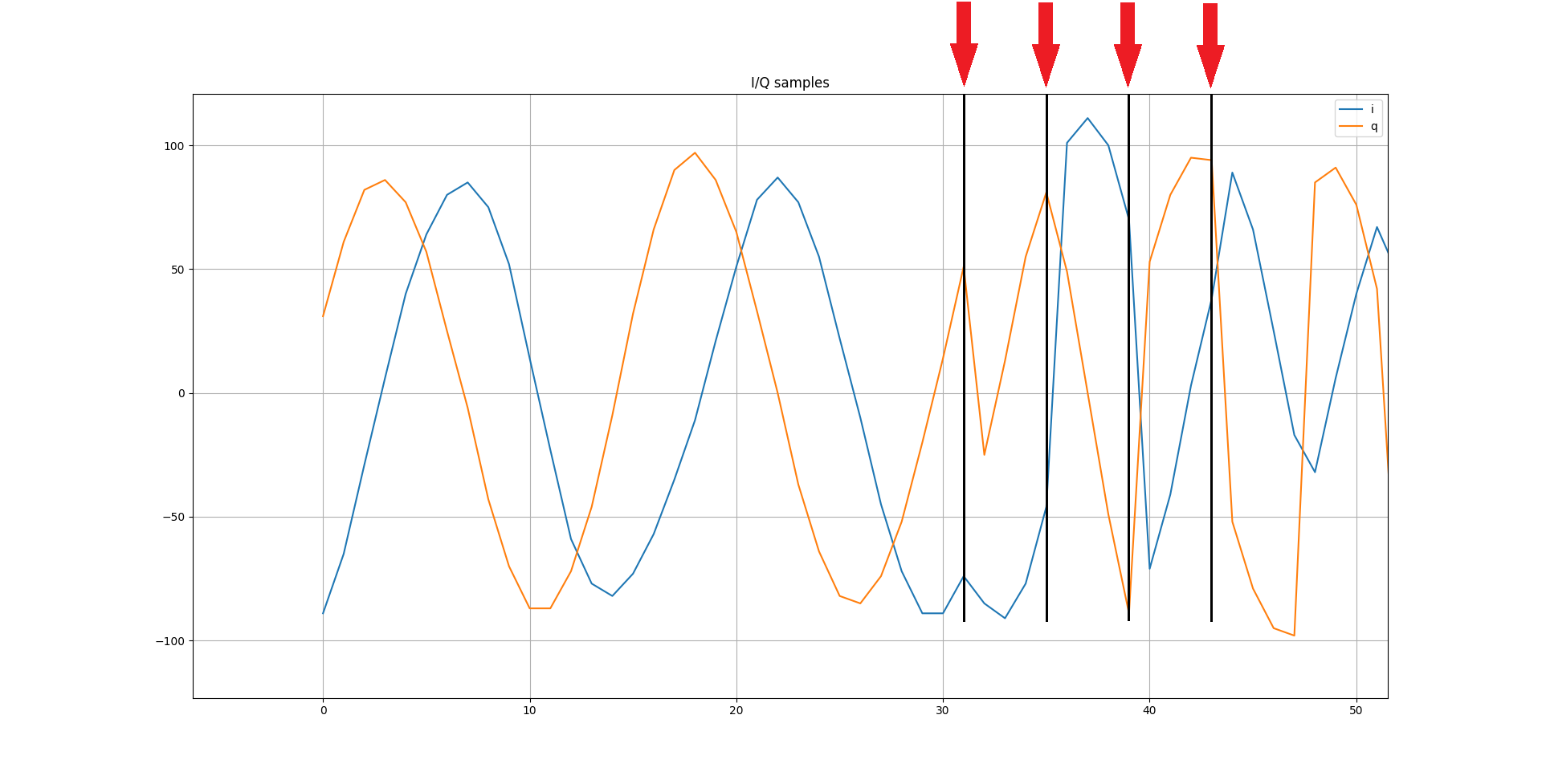
So, I used the rtls_aoa_iq_with_rtls_util_export_into_csv.py file, changing some parameters, and the Python script provided by SimpleLink Academy -> RTLS Toolbox -> Angle of Arrival (AoA) to plot the I/Q data from the CSV file. The result is below for antenna 1, where the red arrows indicate where the antennas seem to be switched:

This test was performed with a Master device, with only one slave device connected. The SDK version is 4.40, and the firmware was untouched. The Python section that configures the AoA feature follows below:

        if aoa:
            if rtlsUtil.is_aoa_supported(all_nodes):
                aoa_params = {
                    "aoa_run_mode": "AOA_MODE_RAW",  ## AOA_MODE_ANGLE, AOA_MODE_PAIR_ANGLES, AOA_MODE_RAW
                    "aoa_cc2640r2": {
                        "aoa_cte_scan_ovs": 4,
                        "aoa_cte_offset": 4,
                        "aoa_cte_length": 20,
                        "aoa_sampling_control": int('0x00', 16),
                        ## bit 0   - 0x00 - default filtering, 0x01 - RAW_RF no filtering - not supported,
                        ## bit 4,5 - 0x00 - default both antennas, 0x10 - ONLY_ANT_1, 0x20 - ONLY_ANT_2
                    },
                    "aoa_cc26x2": {
                        "aoa_slot_durations": 2,##RB 1
                        "aoa_sample_rate": 4,   ##RB 1
                        "aoa_sample_size": 2,   ##RB 1
                        "aoa_sampling_control": int('0x10', 16),
                        ## bit 0   - 0x00 - default filtering, 0x01 - RAW_RF no filtering,
                        ## bit 4,5 - default: 0x10 - ONLY_ANT_1, optional: 0x20 - ONLY_ANT_2
                        "aoa_sampling_enable": 1,
                        "aoa_pattern_len": 2,
                        "aoa_ant_pattern": [0,1]
                    }
                }
                rtlsUtil.aoa_set_params(aoa_params)
                print("AOA Paramas Set")

                ## Setup thread to pull out received data from devices on screen
                th_aoa_results_parsing = threading.Thread(target=results_parsing, args=(rtlsUtil.aoa_results_queue,))
                th_aoa_results_parsing.setDaemon(True)
                th_aoa_results_parsing.start()
                print("AOA Callback Set")

                rtlsUtil.aoa_start(cte_length=20, cte_interval=1)
                print("AOA Started")

When comparing my plot to that one shown in https://dev.ti.com/tirex/content/simplelink_cc13x2_26x2_sdk_3_40_00_02/docs/ble5stack/ble_user_guide/html/ble-stack-5.x-guide/localization-index-cc13x2_26x2.html#valid-i-q-samples-for-angle-calculation, it seems that the antenna switching period is much shorter. In the TI's user's guide's picture, the antenna is switched every 16 sample periods, but in my plot the antenna is switched every 3 sample periods. 

Is it really wrong? If so, what could be the cause?

Thanks,

Reginaldo.

  • Hi Reginaldo,

    May I ask you to confirm which SDK you are using? I know you mentioned 4.40 but the python code does not corresponds. In addition you pointed to documentation for SDK 3.40, hence my question :)

    Could you also share a slightly longer extract of the IQ data you collected?

    To finish, an environment without any other RF transmission is NOT an environment without multipath. You will avoid as much as multipath possible by running the tests in an anechoic chamber or outside, far from any reflective surface.

    Best regards,

  • Hi Clément,

    Thanks for helping me again!

    I confirm that I'm using SDK 4.40.00.44 (version shown in CCS, but the folder in my hard drive is simplelink_cc13x2_26x2_sdk_4_30_00_54...) . I pointed out to documentation of SDK 3.40 because the I/Q plot I found there shows the antenna transitions more clearly than in the image I found in the SImpleLink Academy documentation when I searched for it in the Internet:

    I've attached a .csv file with the I/Q samples of another test run.

    About the python code I used, it's similar to the code I found in the SDK 4.40 documentation, except the values of some parameters that I changed in order to get the plots with higher resolution:

    I know that a RF-free environment has nothing to do with a reflection-free one, but I want to ensure that such timings are correct before hiring a period of tests in an anechoic chamber, since such switch period should not be disturbed by RF interference an/or reflections.

    Best regards,

    Reginaldo.

    iq_samples.csv

  • Hi again,

    I figured out why the waveform looked so weird. It was the RF filter configuration. Now it's similar to expected:

    Best regards,

    Reginaldo.

  • Hi Reginaldo,

    Thank you for sharing. As you mentioned, the traces look good now!

    Kind regards,