A related question is a question created from another question. When the related question is created, it will be automatically linked to the original question.
If you have a related question, please click the "Ask a related question" button in the top right corner. The newly created question will be automatically linked to this question.
Based on the previous thread, I am not sure which test option you have selected. Would you mind telling me which tests are you running, why, and what are the lab equipment you want to use?
We need to tests the frequence spectrum to make sure there is no frequence deviation. Now our product has some bluetooth compliance issue, we doubted it's a RF issue, but we need to mesure the current frenquence spetrum now.
The test equipment we used is enclosed.
As for other test details, you can get more informatioin from thest snapshot:
Sorry for the duplicate photoes. We double checked that test equipment works well with other bluetooth device.
Below picture is how we connect the hardware to do the test, we flash the host test program to both TI launch board and target board. But there is no signal detected on the test equipment.
I think there is one more thing wrong with your setup. Actually, the Bluetooth tester is sending out RS-232 frames (not USB). However, if I am correct, the tool has only some USB inputs/outputs. So you need an USB to RS232 converter. Then the RS232 will have only 2 signals (Rx and Tx). Those can be connected on the proper pins.
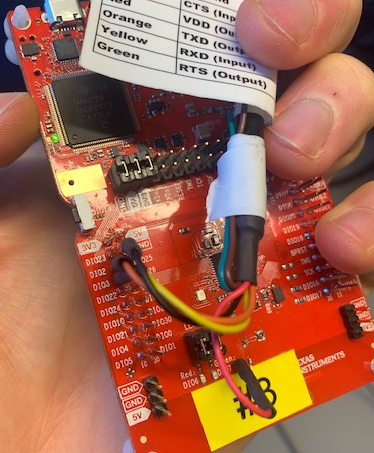
I recommend you run the tests (at least test the connection between the tool and the device) using a Launchpad flashed with the out of the box host_test example. I have attached a picture of some tests I run before (not with the exact same tester). If it not clear, the USB input of the device is used only to power-up the board. The wires connected to my Launchpad are the one coming from the USB-RS-232 converter. As you can see, the out of the box example does not use the RTS/CTS signals. Only the GND, Rx and Tx are connected on my Launchpad. As a side note, the picture does not show the RF connection between the tester and the Launchpad, but this one is of course required (not that on launchpads, you have to flip a capacitor in order to route the RF signals to the CMD output instead of the PCB antenna)
To finish, I don't think I am the best person to help with this Bluetooth Tester - basically because, like you, I am only a user of this tool. Please try to contact the vendor directly. You can also look though their app note if you find something else (here).