


 ....1
....1
.....2
Hi everyone.....
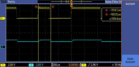
I m using CC2540 on custom board and working on custom bluetooth 4.0 project. At the first screenshot yellow channel of scope shows destination wave to measure pulse-space width. This wave coming from anolog circuit to P0_7of CC2540. The blue cannel shows catching of any external interrupt(rising&falling). For the first screenshot, the time slot (that has variable value, not fixed) beetwen cursors(value is 189.4 us) is expected value. So, external interrupt on P0_7 is working truely. At the second screenshot, this time, blue cannel showing P0_7 logic-0 state(it means if the P0_7 is logic-0 then toggle) after the capturing any edge. So, after the edge capture, checking the P0_7 state working truely(also, logic-1 state checked).
What i want to?.. I want to measure pulse-space width with 16-bit timer(TIMER1) and save to variable. If the measured pulse-space width with the timer1 is in the destination time slot, then the data array which is coming from analog circuit will place to uint8 array after the evaluation. The code fragments like this;
-For external interrupt init;
P0DIR =(0x07); //P0.7-P0.3 as input- P0.1,P0.2, P0.0 as output/leds-buzzer
P0SEL =(0x80); //P0.7 as peripheral others gpio
PICTL |=0x00; //Port0, inputs 7 to 0 rising edge
P0IEN |=0x80; //P0.7 interrupt enable
IEN1 |=0x20; //Port0 interrupt enable
-For ISR,
#pragma vector=P0INT_VECTOR
__interrupt void P0_isr(void)
{
P0IFG=0x00;
P0IF = 0;
//Need INT0 to trigger on any edge,so xor LSB
PICTL ^=0x01;
_ _ _
//Save Timer/Counter1 into variable to compare
delay = T1CNTL;
delay|= (T1CNTH<<8);
//Check whatever pulse or space
if (P0 & 0x80)
{
P0_2=~(P0_2);
event = 0;
}
else
{
P0_1=~(P0_1);
event = 2;
}
//Set to event to select correct state
if(delay > UD_MIN && delay < UD_MAX)
{
event += 4;
}
else if(delay < KD_MIN || delay > KD_MAX)
{
//There is no correct event occur because of noise or erroneous
//so, reset state to initial state
Reset();
}
_ _ _
//Clear Timer/Counter1 to calculate one other pulse-space time
T1CNTH=0;
T1CNTL=0;
}
-For Timer1 Init;
T1CC0L = 0;
T1CC0H = 0;
T1CTL = (T1CTL & ~(T1CTL_MODE | T1CTL_DIV)) | T1CTL_MODE_FREERUN | T1CTL_DIV_32;
-For 32Mhz Clock;
SLEEPCMD |= OSC32K_CALDIS;
// Change the system clock source to HS XOSC and set the clock speed to 32 MHz.
CLKCONCMD = (CLKCONCMD & ~(CLKCON_CLKSPD | CLKCON_OSC)) | CLKCON_CLKSPD_32M;
// Wait until system clock source has changed to HS XOSC (CLKCONSTA.OSC = 0).
while(CLKCONSTA & CLKCON_OSC);
*****AS Result;
I did not read timer1 value truely. So i need to help. Timer1 working free run mode and time division is 32.
Thanks For All......

