This thread has been locked.

If you have a related question, please click the "Ask a related question" button in the top right corner. The newly created question will be automatically linked to this question.

CCS/CC2640R2F: Issues when achieving uart low power design.

Part Number: CC2640R2F
Other Parts Discussed in Thread: CC2640

Tool/software: Code Composer Studio

previously on this issue:

e2e.ti.com/.../2787109

Now my issue is when switching uart RX pin from  GPIO with interrupt to uart function pin, the pinhandle variable is modified somewhere i'm not aware of.

My design:

Do not initialize uart in the initialization of the uart task and configure rx pin as input with interrupt.wait

initialize uart when necessary, for example there's data to be sent, remove pin configuration of RX pin ( input& interrupt) and init uart (so the rx pin will be used as uart function)

After transmission, in the uart_write_callback, close uart and configure RX pin and input with interrupt.

When data coming from the host, the exit interrupt on rx pin would be triggered and then re-init uart and start to receive data

(the rx part is remained to be completed, so no detail presents here)

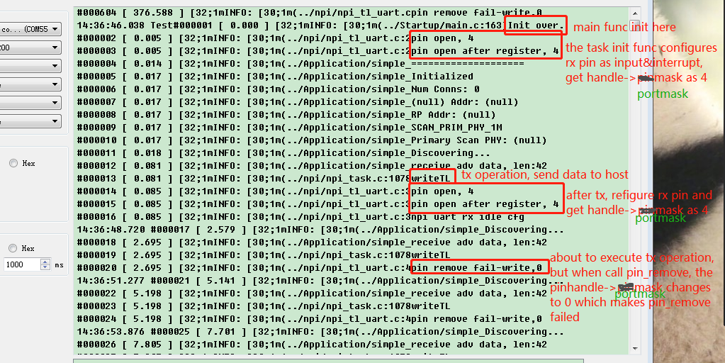
When i complete the design and run the code, the program crashes down. Finally i find that pin handle of the rx pin is modified unaware.

The log:

corresponding codes:

static PIN_Handle pinHandle;
PIN_Config pinConfig[] = {
  CC2640R2_LAUNCHXL_UART_RX | PIN_INPUT_EN | PIN_PULLUP | PIN_IRQ_NEGEDGE,
  PIN_TERMINATE  // Terminate list
};

static void Temp_uarthalinit(void)
{
    UART_Params params;

    // Initialize the UART driver
    UART_init();

    // Configure UART parameters.
    UART_Params_init(&params);
    params.baudRate = NPI_UART_BR;
    params.readDataMode = UART_DATA_BINARY;
    params.writeDataMode = UART_DATA_BINARY;
    params.dataLength = UART_LEN_8;
    params.stopBits = UART_STOP_ONE;
    params.readMode = UART_MODE_CALLBACK;
    params.writeMode = UART_MODE_CALLBACK;
    params.readEcho = UART_ECHO_OFF;

    params.readCallback = NPITLUART_readCallBack;
    params.writeCallback = NPITLUART_writeCallBack;

//    PIN_remove(pinHandle, CC2640R2_LAUNCHXL_UART_RX);// modified by zch 20181211

    // Open / power on the UART.
    uartHandle = UART_open(Board_UART0, &params);
    if (uartHandle == NULL)
    {
      // An error occured, or indexed UART peripheral is already opened
      HAL_ASSERT( HAL_ASSERT_CAUSE_UNEXPECTED_ERROR );
    }

    //Enable Partial Reads on all subsequent UART_read()
    UART_control(uartHandle, UARTCC26XX_CMD_RETURN_PARTIAL_ENABLE,  NULL);
    //UART_control(uartHandle, UART_CMD_RXDISABLE,  NULL);


}

void NPITLUART_initializeTransport(npiCB_t npiCBack)//(Char *tRxBuf, Char *tTxBuf, npiCB_t npiCBack)
{
    PIN_State   pinState;
    npiTransmitCB = npiCBack;

    // Open PIN driver and configure chip select pin callback
    pinHandle = PIN_open(&pinState, pinConfig);
    if(pinHandle == NULL) {
        // Error initializing button pins
        SC_Log_info0("fail to open pin");
        //while(1);
    }

    SC_Log_info1("pin open, %d",pinHandle->portMask);
    if (PIN_registerIntCb(pinHandle, NPITLUART_RXPinIntCallback) != PIN_SUCCESS) {
        // Error registering callback function
        SC_Log_info0("fail to register int callback");
        //while(1);
    }/**/
    SC_Log_info1("pin open after register, %d",pinHandle->portMask);
 
    return;
}

static void NPITLUART_writeCallBack(UART_Handle handle, void *ptr, size_t size)
{
    ICall_CSState key;
    key = ICall_enterCriticalSection();

.....
        TransmitCB  //inform uplayer that tx is over
.....

    NPITLUART_RXPinIdleConfig();
    ICall_leaveCriticalSection(key);
}

static void NPITLUART_RXPinIntCallback(PIN_Handle handle, PIN_Id pinId)
{
//    PIN_clrPendInterrupt(handle, pinId);
    if(PIN_remove(handle, pinId) != PIN_SUCCESS)
    {
        SC_Log_info0("pin remove fail");
        return;
    }
    SC_Log_info1("pin open, %d",handle->portMask);
    SC_Log_info1("pin remove pinId %d", pinId);
    Temp_uarthalinit();
    SC_Log_info0("hardware io interrupt");
}

void NPITLUART_RXPinIdleConfig(void)
{
    PIN_State   pinState;
//    UART_readCancel(uartHandle);
    UART_close(uartHandle);
 
    // Open PIN driver and configure chip select pin callback
    pinHandle = PIN_open(&pinState, pinConfig);
    if(pinHandle == NULL) {
        // Error initializing button pins
        SC_Log_info0("fail to open pin");
        //while(1);
    }

    SC_Log_info1("pin open, %d",pinHandle->portMask);
    if (PIN_registerIntCb(pinHandle, NPITLUART_RXPinIntCallback) != PIN_SUCCESS) {
        // Error registering button callback function
        SC_Log_info0("fail to register int callback");
        //while(1);
    }/**/
    SC_Log_info1("pin open after register, %d",pinHandle->portMask);
 
    SC_Log_info0("npi uart rx idle cfg");
}

uint16 NPITLUART_writeTransport(uint8 *p, uint16 len)
{
    ICall_CSState key;
    static bool flag = true;

    if(PIN_remove(pinHandle, CC2640R2_LAUNCHXL_UART_RX) != PIN_SUCCESS)  //opration here failed if pinhanble->portmask is modified
    {
        SC_Log_info1("pin remove fail-write,%d",pinHandle->portMask);
        return 0;
    }
    key = ICall_enterCriticalSection();

    Temp_uarthalinit();
    UART_readCancel(uartHandle);

....
uart_write...
...

    ICall_leaveCriticalSection(key);

    return TransportTxLen;
}

Codes may seems a lot here but logical relation ship is simple. Please pay attention to it T_T

1.why i must use pin_remove before re-init uart in NPITLUART_writeTransport function, i tried without this function, the program would directly crash down, so it's necessary.

Q:

Operations about pinhandle is simply above, please help me to analyze what's wrong.

Looking forward to your reply.

  • Hi CL,

    I suspect that your "NPITLUART_RXPinIdleConfig" function is the problem together with "NPITLUART_initializeTransport". In short, you seem to be performing multiple PIN_open on the same handle without always closing it.

    To do what you are trying to do, you only need to do PIN_open one single time, then use the PIN_add() and PIN_remove() APIs to add/remove the RX pin from the PIN handle.
  • Hi M-W

    M-W said:
    you seem to be performing multiple PIN_open on the same handle without always closing it.

    When should i close it? I use pin_remove function to clear old configurations on the IO, i don't know when to close it, in fact, i even don't know it's mean to close the io or nullify the handle itself, so this maybe the problem.

    If there should be an operation of uart_close, where should i put it in? After pin_remove or right before i call pin_open again?

    I failed to find similar projects to learn, could you please introduce me some documentation or example project to learn about rules about handling pins?

    Looking forward to your reply. Thank you very much!!!

  • Hi CL,

    The rules are quite simple, open is called before using a driver, close is to be called when you are not going to use the driver any more.

    In the case of the PIN driver, you can add and remove pins to the handle without closing the driver. This means you only need to open it once, save the handle, and then use this to add/remove the pin as needed (as suggested in the SPI "Wake on chip select" example we talked about earlier).

    This means that for you, the UART_close need to be called before PIN_add() and that PIN_remove() need to be called before UART_open. PIN_open you should only do once during start up and then re-use that handle.
  • Hi M-W

    I modified my codes following your suggestion and it did work. I tested the power consumption and it can achieve about 1.5 uA when static.

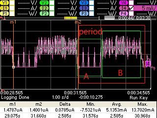
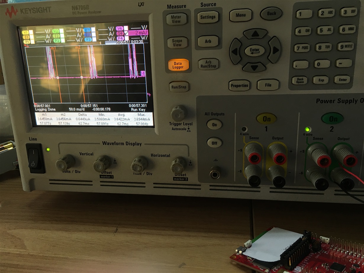
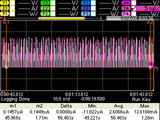
    But there's also new problems, during idle (i mean the device is not scanning), there're unknown current peaks which is about 8 mA. Data are from keysight N6705 at sampling period 0.02048. Pic:

    pic 1 illustration: since i'm using scan period 2*1.28s = 2.56s, scan duration 160*10ms = 1.6s,the pic above shows the scan parameters are running correctly, but the front part, which i would like to name it part A, should be in low-power status but there are unknown current peaks, information about the peaks below:

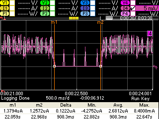
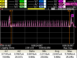
    pic 2 illustration: there are 4 peaks in the pic, the current varies from about 5 mA to 8 mA.

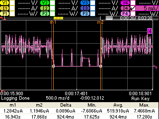
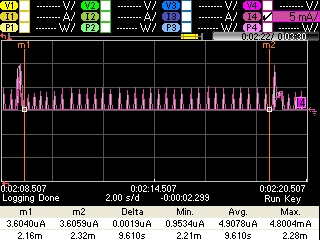
    pic 3 illustration: under some situations, there are unknown active behaviors too, detail about it:

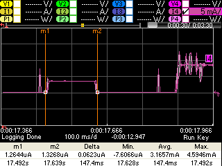
    pic 4 illustration: it's about and 3.2mA (what kind of active operation could cause such current? it's like MCU's awake) and lasts about 150ms.

    pic 5 illustration: as to peak numbers, it's not fixed to 3 or 4, in fact, it's changing, right after initialization, there're about 7 peaks and as the device runs, it finally decrease to 2 peaks, the current is at the same level.

    My design:

    My project is only an observer, it listens to the environment and when gets specific advertising reprot(check by application layer), it would use uart to send these data to host, during the tests above, no uart receive actions happened, there're only tx. Therefore, i think most events should happen during part B or right after it, there should be nothing else after scan, no log, no data out.

    I'm really confused about the current peaks, i know that codes maybe complex, and it's maybe very difficult for you to infer what happened without whole project presented, so just give me some ideal, tell me what you guess, and i would prove it.

    Thanks for what you have done for me, thank you very much.

  • Hi CL,

    As for the small spikes you see, I would assume these to be the recharge pulses, these are to be expected.
    As a reference, you can take the pinStandby example and perform the measurements on that when in standby. You should see periodic small spikes in the same way.

    As for pic 3-4, the small 150ms period of 3.2 mA looks like the device is waking up for a small amount of time to perform some calculation. This is close to impossible to guess on what it could be, but most likely there is some clock set to expire at that time in the application. Can you see this pulse more then once, and in this case, is the period between the two static? If that is the case, you might be able to deduce what clock it might be by looking into ROV when debugging.
  • Hi M-W

    M-W said:
    I would assume these to be the recharge pulses, these are to be expected.

    Recharge for what? Capacitor? Actually, in my board, there's not much capacitors.

    M-W said:
    Can you see this pulse more then once

    Yes, it shows up once in several periods.

    M-W said:
    and in this case, is the period between the two static?

    Actually, it is not static, period of part A is fixed, about 900ms, but during the period, the spikes may shows 2 or 4 times, even more, so the period between two spikes is not static.

    But i would also try to make sure if there is any clock event in my design.

    It's Friday and i am about to go off work, see you next Monday and wish you happy weekend :D

  • Hi CL,

    The recharge pulses are the device re-charging the VDDR capacitors, this to retain the device in standby.
    I suggest you do the base line measurements on the TI examples so that you have a reference for how it could look.

    Regarding the 150ms part, was this part periodic?

    Enjoy your weekend!
  • M-W said:
    I suggest you do the base line measurements on the TI examples so that you have a reference for how it could look.

    Since i'm using my own module, so download the firmware directly into my board is unavailable, the io configurations are not suitable, so i'm keeping looking for ways to solve this problem.

    There's one thing i need to confirm, would simplecentral project go to standby by default? If so, i would flash this firmware to my board to check the re-charge current spikes. If not, which project do you recommend?

    M-W said:
    Regarding the 150ms part, was this part periodic?

    Actually, in my opinion it's not periodic, it's presence is somehow random, but it's duration and current is likely fixed, lasts about 150ms and keep at the level 3.2 mA.

  • Hi CL,

    That is most likely 150ms of active time due to your software. Simple Central is in standby when it is not scanning/connected so you should be able to use this.
  • Hi M-W

    M-W said:
    Simple Central is in standby when it is not scanning/connected so you should be able to use this.

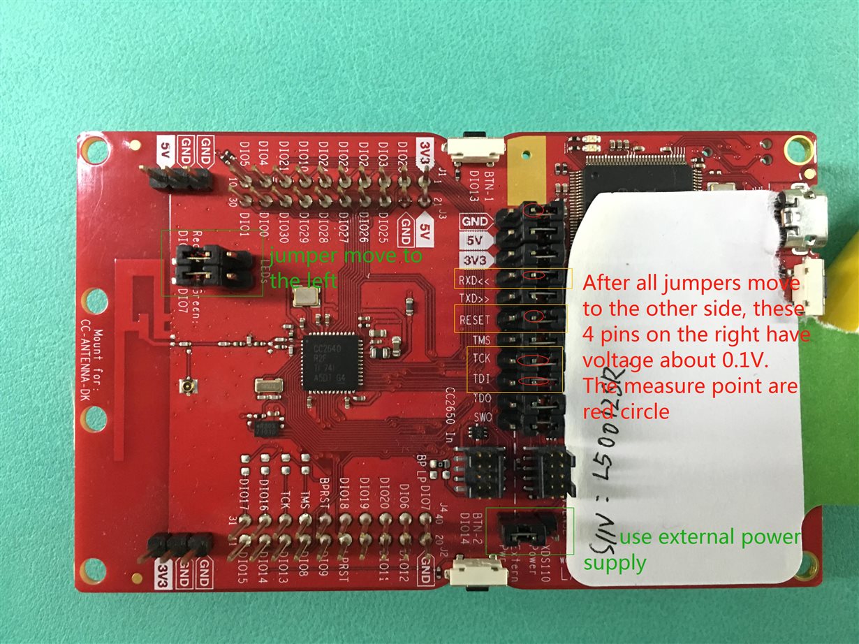
    I think i maybe misunderstand you, i failed. I flash the firmware of SimpleCentral to LaunchPad and do move the jumpers as the pic below describes, use N6705 of KeySight to measure the current, the horizontal line is 4.2mA. Should create a connect before test? I remember there's key operation to select menu so that the simplecentral device would start scanning, is the operation necessary?

    I also tried with SimplePeripheral project, the result's similar, i viewed the document: 

    It seems simple, i dont know what wrong.  what's more, i'm using SDK of version 2.2, does this matter?

  • Hi CL,

    You should also remove the "Ext. Power" jumper. As you have a launchpad, I suggest you try measuring the current with the Simple Peripheral example, just so you are sure you can re-produce the result in the application note before moving on to Simple Central. 

    As all jumpers is disconnected, you should not worry about the value of the pins on the right side, which belongs to the debugger.

  • I tried again with simpleperipheral right after i saw your answer, and failed again T_T

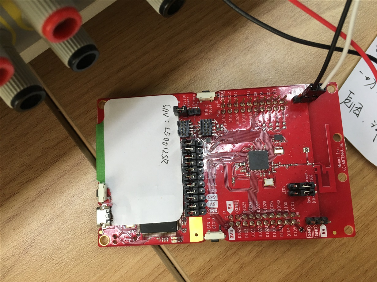
    I did remove all jumpers, ext.power included, but the current keeps at 3.6mA.

    pics:

    Power wire is connected to the board on the upper right corner pins.

    I wanna make sure that the project (simpleperipheral) could enter standby mode without operations after flash firmware into the board.

    Thank you for your time.

  • If I'm following the guide, I get the expected output.

    What SDK are you using when flashing simple peripheral, which example exactly are you running?
    I also suggest trying the pinStandby example, as this should stay in standby until pressing the LP buttons.
  • SDK: simplelink_cc2640r2_sdk_2_20_00_49
    Example path in SDK: C:\ti\simplelink_cc2640r2_sdk_2_20_00_49\examples\rtos\CC2640R2_LAUNCHXL\ble5stack\simple_peripheral
    I would try pinStandby right now.
  • Hi M-W
    I find part of the problem, the library file is modified by me when i was learning and forgot to modify it back, i use another computer with new-installed SDK and flash the firmware into the board, the current now lowers to about 30 uA, both simplecentral and simpleperipheral have similar static current.
    I think the problem maybe hide in the board, i have borrowed a board from my supplier, so let's discuss the issue later.
  • Before the board arrives, let focus on another question.

    Recently, i met a problem, when tx and rx happens very near, rx maybe truncated into two or more parts and lose many data and hard ware interrupt  may triggered more than one time. I have two flag for each of tx and rx , if either event is being processed, uart wont be closed, but this didn't help. I have some guess about this.

    Since in my design,  TX and rx are not sequential, so i need to process these two events individually. Is it possible, that during a tx procedure, rx event happens, and if i close uart after tx done, but rx is not finished, which means rx done haven't happened, rxcallback is not called ( may this happen?), then incoming data would be lost.

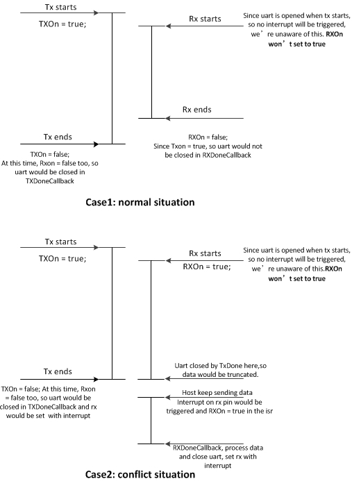
    I draw a pic to describe this scenery:

    Are you agree with me? If so, is there any means i can get the status of receiving data? If not, what's your opinion?

    By the way is this “hand-drawing" pretty? :P

  • Hi CL,

    The 30 uA could be due to the fact the the "RX" jumper is disconnected. Try putting this back again, I would expect this to lower the current consumption (this is due to the RX pin floating if the UART driver is used and the pin is configured to be UART RX).

    Regarding your diagrams, what you say seems to make sense. You would need to perform a check to see if RX is active before closing the driver. During "Close", the UART_readCancel() will be called to stop any potential ongoing reads. If a read is currently active, the read callback should be called with the data received up to that point, the rest would get lost as the receiver is turned of.

    There is not any easy solution to this in your case. If you have a frame format that contains the length, you could leverage this to have more control of when you are waiting for a frame and when you are processing an frame.
  • Hi M-W

    M-W said:
    The 30 uA could be due to the fact the the "RX" jumper is disconnected. Try putting this back again, I would expect this to lower the current consumption (this is due to the RX pin floating if the UART driver is used and the pin is configured to be UART RX).

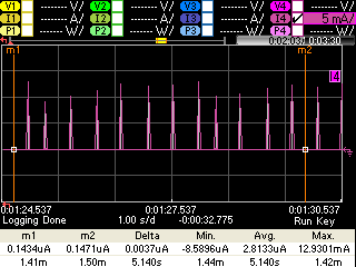
    Thanks to your guide, i have made it! I need to make sure one thing, are all spikes in the pic below used for re-charging?

    pic 1

    avg current:

    pic 2

    In order to get more detailed data, i measured interval and spike current value, here are them:

    interval: 447.5ms  434.4ms  477.9ms   312.8ms   495.3ms   417.1ms   495.3ms   417.1ms  

    spike current: 12.96mA  10.14mA  10.87mA  12.46mA  11.17mA  7.6mA  12.56mA  13.00mA  9.99mA  11.01mA  12.4mA  11.03mA  7.79mA  12.61mA 

    Both interval and spikes seem various, i can't draw obvious rule from these, how could i tell apart re-charging spike and others? Or in what situations, we can make sure that a spike must be a re-charging spike?

    Regarding the left part in your answer,calling UART_readCancel() would lead to truncating the data and losing part of it, so is there anyway to get status of the receiving event before it's done? If so, i would delay the action of uart_close, and receive a complete frame successfully. As we know, even if there's length byte if the frame, losing data would cause discard, communication for this time is ruined.

    Thank you for your time, learnt a lot from you.

  • Hi CL,

    The looks like re-charge pulses, they are adaptive to some extent, so the duration between two pulses could vary.
    You could tell it is a re-charge pulse by the length from it, as waking up the RTOS takes a significant amount of time, causing a wider pulse.

    Also, try measuring the avg. current from the end of a pulse (low level) to the end of the next pulse (basically, 1 idle interval + 1 pulse).

    Regarding UART, there is no good way to know that the read is currently active. You can do a direct access to the UARTCC26XX_Object structure (be careful wen doing this as it is not meant to be accessed outside of the driver) and look at the "readCount" that should indicate how many bytes you have currently read.
  • God, it didn't work. T_T

    I add a read operation before txwritecallback set rx pin to interrupt, if the readcount is greater than 0, it would give up the operation.

    And i also used time expiry instead of rxcallback to configure rx pin. (the timer is set with 10ms, while i send 50 bytes to the board at 115200)

    But all these above didn't work. It seems that the error happens in the physical layer, because rxcallback showed that the borad only receive about 6 bytes, and then recalled again with receiving only 3 or 2 bytes. It seems that only if rxcallback executed, the error will keep going.

    So, what's the mechanism of call rxcallback i register to uart driver.

    By the way, i also tried add an pullup resistance, it seems make no difference.

    Do you have any other idea?

  • Hi CL,

    The concept "timeout" is not supported in callback mode. There is no special mechanism to the RX callback, it will be called when you have either read what you expected, have an UART error or someone call "UART_cancelRead/UART_close" and there is pending data.

    Unless your issue is floating lines, adding pull-ups is not the solution. What you are trying to do is far from an easy (or ideal) solution. I would like to suggest, again, that you look into adding the concept of flow-control to your project to better handle TX/RX collisions. This also means you would not need to do the UART_close->PIN Interrupt hack in order to save power as the sending party would have to set "Request to send" and await "Clear to send" before sending data.
  • I choose not to use flow control because of the limitation of whole project design, flow control need two more pins, this requires more resource of the host.

    Today i have tried to sniff data with logic analyzer, the result shows that data sent from host is correct, the problem may lie in the physical layer, during wake up from standby and initialize uart to receive, this part is invisible for me, so now i'm preparing to test: if the host gives a negative edge on rx pin before sending data,could cc2640r2 receive data completely? This means a wake up action before sending uart data, and it only cost software modification. If this plan is possible, i would suggest my team to use this plan.
    Thanks for guidance you give me all along this period, thank you very much.

  • Post the analyzer sniffing result here, in case you have any brainstorms:

  • My team refused my plan, so it's decided to work this problem out.

    Bro, it looks really like a software problem. Since i'm using timer to set rx pin to standby configuration, i extend timer period to 5 seconds and make the host send two packets during the 5 seconds. I find that the first packet (wake up from standby) is always wrong, and the second packet is always right, What's more, lowering baud rate from 115200 to 9600 makes the issue happens nearly every time. 

    I even try to move all the application layers, call uart write in rxcallback, which means echo back data received directly, the result is similar, the first packet after waking up from standby turns into mess while the next packet is echoed back correctly.

    Do you have any idea about this? My leader tells me to operate registers directly, emmmm, if you have no advise, please give some guidance or example code on operating registers with uart, i will appreciate it.

    Looking forward to your reply.
  • Hi CL,

    As mentioned very early in this thread, the "RX interrupt" work around will always mean you loose the initial data, even in the best case scenario. What you are trying to do is not particular easy even in the scenario where you can fully control the RX/TX flow yourself. If you have no chance what so ever to get actual flow control into the device, I would suggest you try to centralize the UART in your own task.

    Doing direct register access will not help you with the fundamental problem here in any way. 

    Some pseudo code:

    void myPINCallback() {
      if (uart not open) {
        Remove PIN interrupt
        open UART
        start READ
      }
    }
    
    void myReadCallback() {
        If done, post event READ_DONE
    }
    
    void myUARTTask() {
      
      UART write in blocking mode
      UART read in callback mode
    
      while(1) {
        event = Event_pend(...);
        
        if (event == DO_WRITE) {
           if (uart not open) {
             Remove PIN interrupt
             open UART
             start READ
           }
           UART_write(...);
        }
        
        if (event == READ_DONE) {
           ... what ever to do
        }
    
        readActive = (uartCC26XXObjects[0].readCount > 0) ? 1 : 0;
        if (readActive == 0) {
           ... Turn of UART, configure as PIN interrupt
        }
      }
    }

    Another possible "workaround" for your write/read collisions is to simply swap the sensor controller UART TX port with the application TX one. This means you can allow the TX part to operate independent of the RX while you are free to control when to send out the Log statements which means you can better sync it with your RX operation. 

  • Hi M-W

    Very happy to see your reply and appreciate of your guide code. I think i missed to tell you something important, i accept losing data, that's reasonable, due to waking up from low power mode, as we know.

    But now my issue is, it happens sometimes that the whole packet turns into mess, which means i lose al data making sense. Losing certain mount of data is acceptable, we can deal with this by processing frame protocol, but missing whole packet during one communication is an error should be solved.

    17:33:44.657 000JK000005,TEM=032.65,CH4=35%,VALVE=ON  //tx
    17:33:44.707 �諅殥r勃bY1Y
    17:33:45.558 000JK000005,TEM=032.65,CH4=35%,VALVE=ON  //tx
    17:33:45.615 0JK000005,TEM=032.65,CH4=35%,VALVE=ON

    The first and third line is data the host send. The second and fourth line is the echoed back data, line 2 means missing whole packet, while line 4 means missing 2 bytes,acceptable.

    Sorry i maybe confusing you.

  • Hi CL,

    I think this loss is simply due to a "conflict of interest" between your write and read split up. This is why I recommended to create a unified task to get better control of the write/read situation. Alternatively, doing the SCE TX switch.
  • Hi m-w
    I think the problem is not simply data loss, and i have already made uart a single task.
    During recent several days, i tried another method. Since i think i have run out of ways to solve this problem in SimpleCentral part, so i tried to write a test program on another board which plays the role of host. In the host board, before sending data to simplecentral, i gives a negative edge and delay about 10ms, and then sending data. In this way, simplecentral could wake up from standby and receive data correctly, without losing or making bit errors.
    So, the problem is solved by this way. But i think, there's something wrong after waking up from standby, and it should be easy to find, it's not only about losing data but also improperly returning from uart read and bit error. If you need, i can provide my code of uart part.
    How's your Christmas? Wish you great holiday!
  • Hi CL,

    Just fine thank you, enjoy your holiday as well!

    Example code is always helpful, if it is possible, could you provide a small "dummy project" containing your UART setup and that has the same problem as you see?

    As it works when you allow for the device to fully wake up from standby, I assume the problem is related to the case when you start to send data before the device is ready, which could cause bit and framing errors.
  • Hi M-W

    Happy to see your reply in the new year.

    M-W said:
    I assume the problem is related to the case when you start to send data before the device is ready

    Actually, i didn't send data before the device is ready, the device just wakes up from standby by the interrupt on RX pin, my opinion's similar with yours, i think the device receives data before it's ready from wake up, although data incoming is correct, the device misunderstanding the data, this leads to bit errors.

    As to example project, sine my working pc is encrypted, so i need sometime to make it. I would close this thread after uploading the project.

    Thanks for your help. Best wishes in the new year.

  • Hi CL,

    Happy new year.

    Let me know when you have been able to put the example together. Regarding the "misunderstood" data, this could simply be the case where the UART receive is started mid transaction, where it picks up an arbitrary data bit as a START condition.
  • Hi CoolLeopard,

    I read this thread and just want to share my experience. I have successfully implemented UART and achieved standby current of 1.1uA at my previous CC2640R2F product development. Here are my tips below to achieve Low Power using UART if you are using CC2640R2F LP.

    1. You need to shutdown the SPI External Flash. The C function for that can be found at Board.h
    2. At SDKv1.40 calling Uart_close() does not close the Uart port and still consumes current. I do not know if that is fixed at SDKv2.20. See, post below.

    e2e.ti.com/.../2285390

    -kel
  • Very happy to see your reply, i'm still struggling with the encrypt software on pc, please wait for me.
    Best wishes.
  • Hi Markel

    Very happy to see your reply, i will read the post, but before that, could you please tell me the meaning of:

    Markel Robregado said:
    1. You need to shutdown the SPI External Flash. The C function for that can be found at Board.h

    I have find Board.h at :C:\ti\simplelink_cc2640r2_sdk_2_20_00_49\source\ti\ble5stack\boards\CC2640R2_LAUNCHXL

    Search result of keyword "flash" are:

    1.
    #define Board_shutDownExtFlash() CC2640R2_LAUNCHXL_shutDownExtFlash()
    2.
    #define Board_wakeUpExtFlash() CC2640R2_LAUNCHXL_wakeUpExtFlash()
    3.
    #define Board_SPI_FLASH_CS      CC2640R2_LAUNCHXL_SPI_FLASH_CS
    #define Board_FLASH_CS_ON       0
    #define Board_FLASH_CS_OFF      1

    which of the above is the right one?

    What;s more, could you please tell me why the flash of SPI should be closed? The launch pad of CC2640R2F is quite clear, there's only one chip (cc2640r2f itself) on the board.

    Looking forward to your reply for more detail.

  • Hi CoolLeopard,

    The C function to shutdown the SPI External Flash is Board_shutDownExtFlash();. Call that at Simple Peripheral Init.

    CoolLeopard said:
    What;s more, could you please tell me why the flash of SPI should be closed? The launch pad of CC2640R2F is quite clear, there's only one chip (cc2640r2f itself) on the board.

    The CC2640R2F LP has the SPI External Flash see schematic diagram. The SPI External Flash at CC2640R2F LP consumes the highest current on the board. Even if you are not reading or writing to it, current is still being drawn, that is because the SPI External Flash is in idle or standby state. So to completely turn off or shutdown the SPI External Flash call Board_shutDownExtFlash(); at Simple Peripheral Init.

    I suggest you familiarize yourself with achieving low power modes using the CC2640R2F Launchpad and Simple Peripheral. The low power modes are Standby Mode and Shutdown Mode. The Standby Current as per datasheet is 1.1uA. Shutdown Current as per datasheet is 0.1uA

    Procedure to measure Standby Current using Simple Peripheral:

    1. Call Board_shutDownExtFlash() at SimplePeripheral_init().
    2. Disable advertisement at SimplePeripheral_init(). initialAdvertEnable = FALSE;
    3. Rebuild All Simple Peripheral then flash to CC2640R2F LP using SmartRF Flash Programmer2.
    4. Measure current using Keysight DC Power Analyzer.

    Procedure to measure Shutdown Current:

    1. Call Board_shutDownExtFlash() at SimplePeripheral_init().
    2. Call Power_shutdown() after button press or after 5 seconds RTOS Clock. Refer to Pin Shutdown Example Program for reference.
    3. Rebuild All Simple Peripheral then flash to CC2640R2F LP using SmartRF Flash Programmer2.
    4. Measure current using Keysight DC Power Analyzer.

    So at your application when you use UART or other peripherals, then you close it. If you do not measure Standby Current of 1.1uA either the UART or the other peripherals is consuming current.

    -kel

  • Hi MW

    I finally make the project!!! Take me whole day long!

    uartErrorPrj.7z

    To use this project, you should be aware of:

    1. The project is base on CC2640R2F, SDK: simplelink_cc2640r2_sdk_2_20_00_49

    2.Log uart is completed by sensor controller, the TX pin is DIO5, the RX pin is DIO4 (unused here)

    3.To print log, you should add this sentence: Idle.addFunc('&sc_uartLog_flush'); to cc2640_r2_csdk.cfg used in your project

    4.The baudrate of the hardware uart (DIO2 DIO3) is set to 9600, under this condition, the RX can nearly never success, you can change it to 115200 in npi_tl_uart.h file.

       Under the condition of 115200, things would get much better but this also means difficult to reappear the problem, so i set it to 9600.

    What's more, i'm sorry for the format chaos, exporting the project from encrypted pc lead to losing of format. 

    To do the test, you could send some data to hardware uart, it would echo it back. Then you can find the problem.

    Thank you for your patience and looking forward to your opinion.

    Best wishes.

  • Hi Markel
    Thank you for your answer, it's so detailed and so touching. And i have checked the schematic, there's a external flash. I would try as you told me.
    Thanks again, Your share helps me make it much more clear about the board, it's so kind of you.
    Hope you make great fortune in the new year! :D
  • I CL,

    I will try to look into your example. I'll let you know when I've had time to do so.
  • Hi M-W

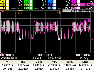
    I'm sorry that this thread can't be closed, because today when i measure power consumption of my board with connected to the host board (they are connected by uart), i find that only if i connect them together, the power consumption would rise.

    Here are data:

    board                                                    static avg current         periodic avg current (including the RF action)

    my board only                                            1.5uA                                 93uA

    board+emulate uart connected                 2.0uA                                  113uA

    board+emulat uart+hw uart connected     4.9uA                                 130uA

    and pics:

    I have made the uart tx pin as normal ios and output high with pushpull, the rx pin as input pin with interrupt and pullup.

    The host device has also made tx and rx pin with pullup.

    An increase like the emulate uart is acceptable, but increase about 2~4 uA is too much.

    Do you have any idea about this?

    Looking forward to your reply.
  • Is this current increase when connecting the UART ports physically? If this is the case, I would assume it to be related to leakage somewhere. Is this increase with UART activity? In that case, what is the resulting value of the pull-up resistors used (keep in mind that these will directly impact power consumption when active).
  • Hi M-W

    Very very happy to see your reply!

    It's the first case:

    M-W said:
    Is this current increase when connecting the UART ports physically? If this is the case, I would assume it to be related to leakage somewhere.

    Once connected, it influences the base line of the current, so I think it's the first case, but when i test the ios connected to each other, i find they're all at high level, so theoretically, there shouldn't be any leakage, by the way, if the voltage of the connected ios are different, does it matter? For example, voltage of host board's rx tx is 3.286, while that of BLE borad is 3.29, would it lead to leakage?

    Missing you in days struggling with bugs and issues.

  • Hi CL,

    If it increases the base line when connected, I would absolutely look into leakage on the lines etc. Any difference in voltage level between the boards could potentially cause leakage. What is the value of your pull-up resistors for example?
  • Hi M-W

    Sorry for delay due to meeting.

    M-W said:
    What is the value of your pull-up resistors for example?

    Actually, i didn't use any of external pull-up resistors, i configured the IOS with pullup, so it's internal pull-up, i'm not very sure about the resistor value.

    What's more, i found that only if connect the GND of the host board to the device board GND, the current would rise about 0.5~1 uA, is it normal case?

    Your real-time reply is pleasure in  boring meeting.

    Best wishes.

  • Hi Cl,

    I have had a quick look at your code and while it is much to try to understand, I have some small comments and maybe a path you can explore to why you are seeing errors.

    Starting with the general comments, I see that you are basing everything of NPI. Is there a reason for this?
    If you don't need the NPI functionality per say, I would suggest you work on your own solution not basing it of NPI.

    Regarding the path you should look more into is "What happens when I have continuous RX, and no TX".
    I can see that when you wake up from standby, you start the UART + a timer. The timer is then later responsible for re-configuring the "wake up" functionality you implemented.

    The problem I see here is that the Clock callback also is responsible of the "read is active" flag which is a bad idea, as it makes no checks what so ever before clearing this flag. This means that you could potentially hit the clock callback mid transaction, kill the UART, setup the pin interrupt and then start everything over again due to the ongoing UART activity.
  • Hi M-W

    Very happy to see your reply.

    M-W said:
    If you don't need the NPI functionality per say, I would suggest you work on your own solution not basing it of NPI.

    In fact, i have clear unnecessary codes in the project. So, it maybe just keep the name of "NPI".

    M-W said:
    you start the UART + a timer. The timer is then later responsible for re-configuring the "wake up" functionality you implemented.

    Remember the question of "waking up from standby and there happens to be messy code“, also the reason i provide the example project to you. Because of this problem, i add a timer to close uart receiving instead of closing it in RXDoneCallback.

    M-W said:
    This means that you could potentially hit the clock callback mid transaction, kill the UART

    Yes, according to the current project, this problem do exist, i haven't try to solve this, but i think, it could be solved by reading uartCC26XXObjects[0].readCount you told me.

    Looking forward to your reply.
    By the way, i would try to write my own solution as you suggested, but before that, i need to make this problem clear and finish the current program version.

    Best wishes.