This thread has been locked.

If you have a related question, please click the "Ask a related question" button in the top right corner. The newly created question will be automatically linked to this question.

CC1101 Power amplifier, side lobes/harmonics

Other Parts Discussed in Thread: CC1101

I am having problems when adding a PA tot he front end of the CC1101 circuit.

I am using the CC1101 at 315MHz the values for the Balun and the filter where taken from Ref  Design swrr046a.zip (see below).

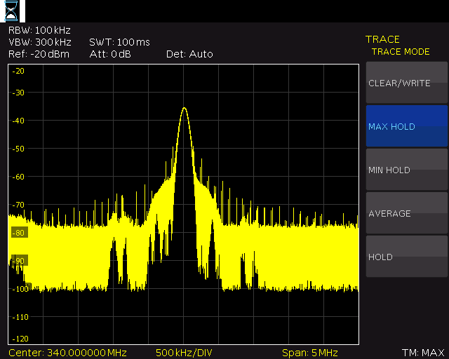
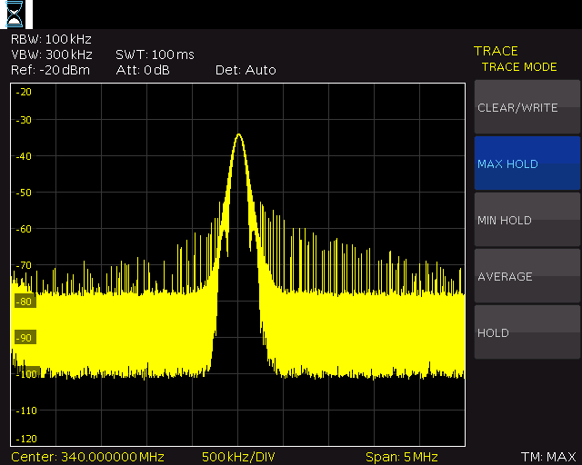
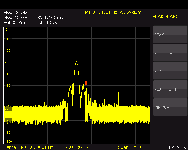
The problem is that this design is producing side lobes/harmonics that are interfering with devices on adjacent channels.

Any help to eliminate these unwanted signals would be appreciated

Ref design of CC1101 used 2248.swrr046a.zip

PDF of PA schematic 4718.PA.pdf

  • Jeromy, Can you post some of the spectral plots you are referring to? /TA
  • Here is the plot with the distortion


    Here is what I am trying to accomplish


  • We have one of the CC1101 evaluation modules.

    We changed the parts over according to the 315MHz reference design.

    We are transmitting a CW at 340MHz and still got the side lobes.

     It seems that the side lobes are not do to the PA design but the CC1101 reference design output.


  • Here is a plot of the

    CC1101EMK433

    with the parts changed to match the 315MHz ref design, transmitting over the air.

    CC1101 was programmed to send full power CW at 340MHz


    Have to find a way to eliminate the side lobes for a "clean" CW

    Thanks for any help

  • Jeremy,

    First it appears that you might be saturating your spectrum analyzer.    I have provided plots of the CC1101 at 433MHz and expect the same results at 333MHz.   If you use a single carrier the 2nd, 3rd and higher harmonics are -51dBc   So if you add a linear power amp which has low harmonic distortion you should see the fundamental and harmonics increase at the same rate.  If not then you should check your matching between the power amp and CC1101.   Then check the matching from the power amp to antenna.   If you are looking at the output of an antenna this is not a good way to characterize your design for radio certification.  Antennas have narrow bandwidths so they tend to reject the harmonics.  For radio certification they use a wide bandwidth horn antenna so if you don't control the harmonics from the output of the filter you might not pass certification. 

    I suggest measuring directly at the point where you connect to the antenna.   You will do this in a 50 ohm system to better understand the absolute values.   If you have a bad match between the antenna and the sources filter output,  then you need to correct this or your amlifier might be going unstable and showing multiple spurs during transmission. 

    I've attached the spectrum plots at 433MHz of single tone carrier which shows its side band spurs.    The other test is to do a power spectrum of the code you are planning to use.  Depending upon the selection you will see different power spectrums. 

    First check to make sure you are not saturating the spectrum analyzer,  then do your measurements with a single tone as shown in the attached plots. The first plot is done at 0dBm and the second at 10dBm.

    Rgds,http://e2e.ti.com/cfs-file.ashx/__key/CommunityServer-Discussions-Components-Files/155/1565.2nd_5F00_harmonic_5F00_433.WMFhttp://e2e.ti.com/cfs-file.ashx/__key/CommunityServer-Discussions-Components-Files/155/7317.2nd_5F00_harmonic_5F00_433_5F00_10dBm.WMF