This thread has been locked.

If you have a related question, please click the "Ask a related question" button in the top right corner. The newly created question will be automatically linked to this question.

TRF7970A: Deseiging with TRF7970ARHBT for a 3.3V logic MCU

Part Number: TRF7970A
Other Parts Discussed in Thread: TPS61241,

Hi Team,
I am using TRF7970ARHBT in one of our projects.
I am planning to connect the VIN pin directly to the battery (4.2V maximum) when the USB in is not available and 5V from the USB when it is available.
My MCU is 3.3V logic.
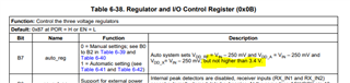
The VDD_X pin cannot be configured to a 3.3V in my case (according to tables 6-1 and 6-2).
I am planning to provide a 3.3V supply from an external regulator to the VDD_IO pin so that my communication with the MCU will be 3.3V logic in that case, can I left the theVDD_X pin unconnected or can I terminate it with proper decoupling. 
From my understanding from a brief reading of the datasheet, VDD_X is the voltage with which the digital I/O takes place, and if I configure it to 3.3V and connect it to VDD_IO I'll not need an external 3.3V regulator. If so during power-up what is the voltage at the VDD_X pin?. If that voltage is higher than 3.3V logic my MCU is gonna damage.
Also, the voltage at the VDD_X, VDD_RF, and VDD_A are programmable, to what value do I need to configure these regulators to get the optimum performance?.
I am planning to use a power switch to disconnect the chip from the battery, the pin VIN will be disconnected, is there any problem when VIN is not power and the pin VDD_IO is powered to 3.3V 

 The TRF7970ARHBT is not available on Mouser or Digikey.

  • Hi Shibin,

    let me check if this configuration you have described well lead to any problems. I will come back to you the next days.

    Best Regards,

    Helfried

  • Hi Shibin,

    if you are looking for the optimal performance, the best would be a 5V supply and setting the device for 5V operation. Your concern is the lower voltage from the battery with max. 4.2V which forces you to the 3V operation mode. I would see the best solution in your case when using a DC/DC boost converter to have a constant fix 5V voltage for the supply. Please see the TI DC/DC boost converter i.e. the TPS61241 (TPS61241 data sheet, product information and support | TI.com)

    Best Regards,

    Helfried 

  • Hi Helfried,
    Thank you for your reply.
    Adding a Boost IC can be considered only as a plan B because of the BoM size.
    What I am planning is to
    Power the Vin from a battery (2.8V to 4.2V) through a power switch TPS2022DR
    I hope VDD_X can b left floating.
    VDD-IO will be powered from a 3.3V regulator since my MCU is 3.3V logic.
    If the voltage t the Vin pin is less than 4.3V, the device will be in 3V mode operation (till the voltage reaches 2.7V)
    What should be the voltage at regulators VDD_A, VDD_RF, and VDD_X in this condition?.
    If VIN is power from a boost converter like you said at 5V, can a 3.3V MCU be able to configure the output voltages at these regulators?. Will it damage my MCU.
    If I am using a power switch to disconnect the voltage t the VIN pin, the VDD_IO pin will be powered from a 3.3V source. that is the VDD_IO voltage will be there without VIN, will this create any problem?.

    The boost IC you suggested has an enable pin.

  • Hi Shibin,

    the VDD_X pin will need at least the blocking capacitor.

    For the regulator setting (register 0x0B I recommend using the setting with all voltages 3V. Under some circumstances the max. and the min. settings lead to problems. Because of the low drop internal regulators the voltages will be, even when Vin = 2.7V, not much lower as Vin.

    From my experience in the lab I have seen no problems when Vin is disconnected and Vio is powered.

    Best Regards,

    Helfried 

  • Hi Helfried,
    Thank you for your reply.
    A decoupling capacitor will be placed on the VDD_X pin.
    If Von is 5V and VDD_X is used to power the VDD_IO pin, what will be the voltage at the VDD_X pin initially.
    We can set VDD_X to 3.3V only by configuring the register. Right?.
    Please correct me if I am wrong.

  • Hi Shibin,

    please see the datasheet register description for the regulator setting. The register default is 0x87 which means automatic setting. the maximum voltage at VDD_X should be 3.4V regarding this description:

    Best Regards,

    Helfried

  • Hi Helfried, 
    Sorry to bother you again,
    I am using TRF7970ARHBT in reader/writer mode.
    My MCU connected to the TRF7970ARHBT will be in sleep mode most of the time.
    Is it possible to wake up the MCU when an external card is detected?.
    I think this is not possible, 
    Expecting your reply.
    Also, its stock is very low in Digikey and mouser

  • Hi Shibin,

    the TRF7970A can not detect a card when in sleep mode. There is an application report which shows a solution with external hardware that might be of interest for you:

    https://www.ti.com/lit/sloa184

    Low stock is not only a problem for the TRF7970A but for the whole semiconductor industry. Hope that will be solved in the near future.