This thread has been locked.

If you have a related question, please click the "Ask a related question" button in the top right corner. The newly created question will be automatically linked to this question.

CC2652RSIP: The copy routine cannot be replicated

Part Number: CC2652RSIP

Hi team,

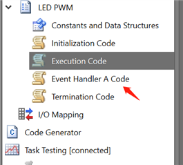
Environment: Sensor Controller Studio. Hardware: purchased development board. Modified routine: LED PWM for LaunchPad.

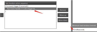
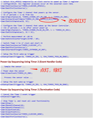
The customer would like to verify the module in the timer2 event trigger section, the copied code in the section is as follows:

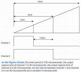
After 1 ms, the timer channel 1 turns on the sensor supply, then channel 2 triggers an interrupt over 1 ms, detects the sensor data inside the interrupt and turns off the sensor supply, and then go into the next cycle.

Change the code as follows: Change the power-on pin to red light and flip the green light inside the interrupt.

Issue: It is now a solid red light, the green light does not turn over, and the customer suspects it does not enter into timer interrupt. What should do next? Does this coprocessor support the imer2 event trigger?

The routine is clearly labeled, completely copied, is there a missing configuration or missing code? The interrupt function is added automatically, using the index as well as the routine is 0.

Could you help check this case? Thanks!

Best Regards,

Cherry

  • Hi Cherry,

    The code appears to be fine as used from the Sensor Controller Studio User's Guide, under "Task Testing" please be sure to remove "Run Execution Code" from the "Task iteration action sequence" and add "Run Event Handler A Code (trigger 0)" from "Available task iteration actions" in its place.  You will also need valid logic inside of "Event Handler A Code" like what was originally in "Execution Code" so that the event accomplishes some task, such as blinking LEDs.

    Regards,
    Ryan

  • Hi Ryan,

    Thanks for your help and the customer follows the step you given. And it did can run to the interrupt, but as fast as 10 ms. The customer intends to implement a trigger event at the us level.

    Thanks and Best Regards,

    Cherry

  • For higher timer resolution, change the clock source (using timer2SetClockSource) from TIMER2_CLOCKSRC_LF (32 kHz) to TIMER2_CLOCKSRC_MF (2 MHz for low power mode) or TIMER2_CLOCKSRC_HFDIV2 (24 MHz for active mode).  Please refer to the Timer 2 Module of the Sensor Controller Studio User Guide.

    Regards,
    Ryan

  • Hi Ryan,

    Thanks for your support.

    The customer did configure as what you mentioned on last post. The function used for the capture code is timer2SetClockSource(TIMER2_CLOCK SRC_HFDIV2);, which is set to 24M.

    And for now, the same code does not enter the interrupt function at the set 100us timing on the SCS debug environment, but integrates the generated file into the CCS environment, after downloading into the cc2652rsip. The interrupt function can be entered at a time set by the customer.

    So what's the reason for that, or how to explain this?

    And so here comes a relevant question:

    Multiple comparison values are set with different channels on the same timer 2, and the time interval that normally enters the interrupt should be the product of the difference between the comparison values and the tick time.

    However, it was found that regardless of the comparison values set to, the time interval between the different channels to enter the interrupt was 4us.

    Is this ok? And is the time axis used by different channels of the same timer to determine with the comparison value unique?

    Thanks and Best Regards,

    Cherry

  • Hi Cherry,

    I'm not fully understanding the description as provided.  The evhSetupTimer2Trigger will only connect to one of four event signal outputs (TIMER2_EV_ID[0 to 3]).  For example, the Sensor Controller Studio User's Guide reference code compares TIMER2_EV_ID1 against TIMER2_EV_ID0, which will trigger 1 ms after the TIMER2_EV_ID0 has set high its GPIO as its timer2SetInitCmpValue is set to 64 instead of event zero's 32 (using a 32 kHz reference), basically forming a PWM given that timer2SetInitCounterTarget is set for 100 ms.  Can you please provide the code they are attempting to implement and specifically what they expect it to accomplish?  Also have them refer to the Sensor Controller Studio SimpleLink Academy Labs if not already done.

    Regards,
    Ryan

  • Hi Ryan,

    The clock used is 24M, the timer 2 period is set to 100us, and the time for two channels enter the interrupt event is 30us and 60us.

    The expected time for the interval enter into interrupt is about 60-30)us, but the measured interval is not 30 us.

    Then they have made all the time values are 10 times larger, and the interval values are just OK. The code is as follows:

    // Set the clock of Timer 2 to 24Mhz
    
    timer2SetClockSource(TIMER2_CLOCKSRC_HFDIV2);
    
    // wait for the clock to settle
    
    timer2WaitForClockSource();
    
    // Set the timer count period
    
    timer2SetInitCounterTarget(2400); //2400 - 100US
    
    /////Reset Timer Channel 0
    
    timer2ResetCcChannel(TIMER_CHANNEL_0);
    
    /////Reset Timer Channel 1
    
    timer2ResetCcChannel(TIMER_CHANNEL_1);
    
    // Generate TIMER2_CCMODE_PULSE_ON_CMP for channel configuration operating modes and events
    
    timer2CfgCcChannel(TIMER_CHANNEL_0, TIMER2_CCMODE_TGL_ON_CMP, 1 << TIMER2_EV_ID0);
    
    // Generate TIMER2_CCMODE_PULSE_ON_CMP for channel configuration operating modes and events
    
    timer2CfgCcChannel(TIMER_CHANNEL_1, TIMER2_CCMODE_TGL_ON_CMP, 1 << TIMER2_EV_ID1);
    
    // Configure the event0 event
    
    evhSetupTimer2Trigger(TIMER_CHANNEL_0, TIMER2_EV_ID0, 1, EVH_TIMER2_TRIG_ON_EDGE);
    
    // configure the event1 event
    
    evhSetupTimer2Trigger(TIMER_CHANNEL_1, TIMER2_EV_ID1, 1, EVH_TIMER2_TRIG_ON_EDGE);
    
    // Set the initial comparison value for Timer 2 capture/compare channels.
    
    timer2SetInitCmpValue(TIMER_CHANNEL_0, 720);//30us
    
    // Set the initial comparison value for Timer 2 capture/compare channels.
    
    timer2SetInitCmpValue(TIMER_CHANNEL_1, 1440);//60us
    
    // Start the timer
    
    timer2StartWithTarget(TIMER2_CNTRMODE_UP_REP);
    
    fwScheduleTask(1);

    Please see the figure below:

    Thanks and Best Regards,

    Cherry

  • Thank you for the detailed information.  How are they measuring the 4 us between interrupt intervals since the event IDs are not tied to GPIOs?  Please note the startup delays involved in going from the Timer 2 event trigger to Event Handler Code execution.

    Regards,
    Ryan

  • Hi Ryan,

    How are they measuring the 4 us between interrupt intervals since the event IDs are not tied to GPIOs? 

    The interval is measured by measuring the time of two led inversion. The led display is made in the event handler A Code corresponding to the event ID.

    Latest Test Results: The interval of 100 ms is accurate, but if 100 us is fast, one event is 10 us and the other event is 20 us in, the interrupt event is not accurate.

    Thanks and Best Regards,

    Cherry

  • I've recently stated that there are startup delays for triggering event handler interrupt code with the sensor controller.  The customer can connect each timer channel event to a GPIO (timer2ConnectEventToGpio) to determine the accuracy of timer 2 execution.  Perhaps the customer should be considering Driver Library or TI Driver code for more accurate interrupt timing.

    Regards,
    Ryan