This thread has been locked.

If you have a related question, please click the "Ask a related question" button in the top right corner. The newly created question will be automatically linked to this question.

Snooping Unknown Packets with CC1101

Other Parts Discussed in Thread: CC1101, TEST2

Hello,


I am working with a medical sensor that transmits some data every five minutes.  I know some specs on the transmission based on FCC information and other published material.  (OOK, 8192 bits/sec, 300khz bandwidth, 76 bits in the packet, 5 ASCII Char Transmitter ID, 402.142mhz).  The 
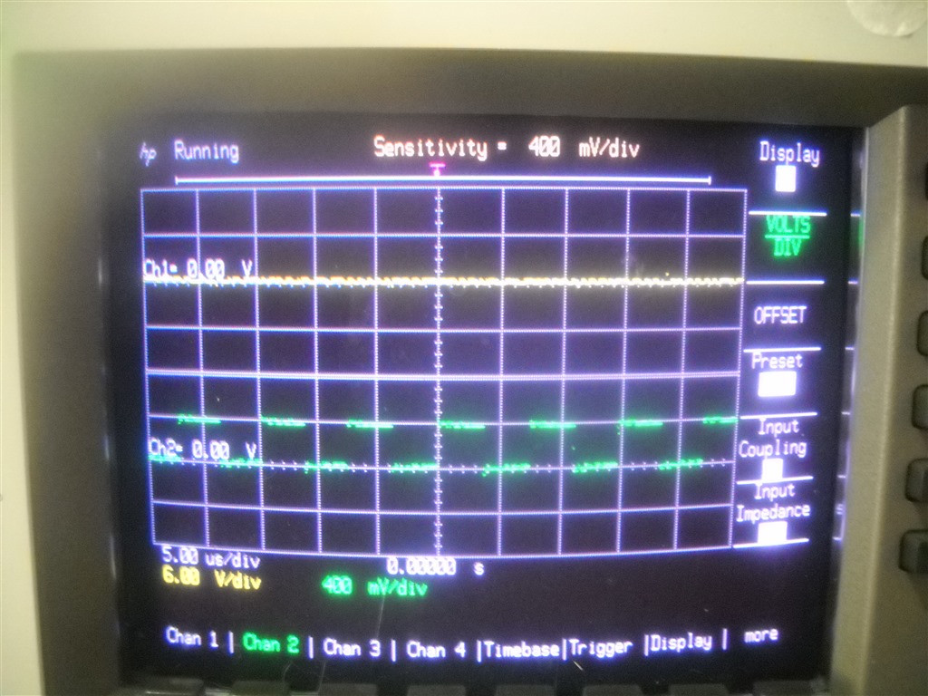
problem is the format of the transmission. I have a radio (being a ham) that can RX on that freq, and tried using my soundcard as a spectrum analyzer to record the signal for manual decoding into binary.  I am pretty sure the sound card is not fast enough to get a sample to use.  Also, with the transmission being only 9ms long, it's hard to catch it completely. 9ms transmission @ 8192 bits is a shade less then < 80 bits.

So the packet structure could look like this:

0xAA            0x??     0x30     0x43     0x54     0x41     0x33     0x??     0xYY
Preamble      Sync     |-------------Transmitter ID------------|    Data      CRC

Assuming the documentation is right, 76 bits = 9ms @ 8192 bits/sec.  72 bits with a nibble left over? Maybe the preamble is longer?

I am looking at (GDO0) to see if I ahve recieved anything, and it never goes to to 1.

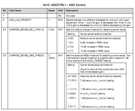
I am using the CC1101 chip with an Arduino board to try and get the raw data of the transmission.  Here are my registry settings:

    SpiWriteReg(CC1101_FSCTRL1,  0x0F);    SpiWriteReg(CC1101_FSCTRL0,  0x00);    SpiWriteReg(CC1101_FREQ2,    0x0F);    SpiWriteReg(CC1101_FREQ1,    0x77);    SpiWriteReg(CC1101_FREQ0,    0x8D);    SpiWriteReg(CC1101_MDMCFG4,  0x58);    SpiWriteReg(CC1101_MDMCFG3,  0x4A);    SpiWriteReg(CC1101_MDMCFG2,  0x32);    SpiWriteReg(CC1101_MDMCFG1,  0x22);    SpiWriteReg(CC1101_MDMCFG0,  0xF8);    SpiWriteReg(CC1101_CHANNR,   0x00);    SpiWriteReg(CC1101_DEVIATN,  0x47);    SpiWriteReg(CC1101_FREND1,   0x56);    SpiWriteReg(CC1101_FREND0,   0x11);    SpiWriteReg(CC1101_MCSM0 ,   0x04);    SpiWriteReg(CC1101_FOCCFG,   0x36);    SpiWriteReg(CC1101_BSCFG,    0x6C);    SpiWriteReg(CC1101_AGCCTRL2, 0x03);    SpiWriteReg(CC1101_AGCCTRL1, 0x40);    SpiWriteReg(CC1101_AGCCTRL0, 0x91);    SpiWriteReg(CC1101_FSCAL3,   0xE9);    SpiWriteReg(CC1101_FSCAL2,   0x2A);    SpiWriteReg(CC1101_FSCAL1,   0x00);    SpiWriteReg(CC1101_FSCAL0,   0x1F);    SpiWriteReg(CC1101_FSTEST,   0x59);    SpiWriteReg(CC1101_TEST2,    0x88);    SpiWriteReg(CC1101_TEST1,    0x38);    SpiWriteReg(CC1101_TEST0,    0x0B);    SpiWriteReg(CC1101_IOCFG2,   0x29);     SpiWriteReg(CC1101_IOCFG0,   0x3F);      SpiWriteReg(CC1101_PKTCTRL1, 0x04);    SpiWriteReg(CC1101_PKTCTRL0, 0x45);   SpiWriteReg(CC1101_ADDR,     0x00);       SpiWriteReg(CC1101_PKTLEN,   0x3D);


Any suggestions or help would be great. I have attached my PDE and libraries.

CC1101_RX.zip
  • Jerome,

    One possibility is to use the CC1101 in serial synchronous or serial asynchronous mode to have it "sniff" what's going on over the air.  Serial synchronous mode is described in this application note:  http://e2e.ti.com/support/low_power_rf/w/design_notes/1170.aspx

  • I am having a lot of trouble getting this to work.  I set the following registers:

    SpiWriteReg(CC1101_PKTCTRL0, 0x10);
    SpiWriteReg(CC1101_IOCFG2,   0x0C);
    SpiWriteReg(CC1101_IOCFG1,   0x2E);  //0C = Data, 0B = Clock
    SpiWriteReg(CC1101_IOCFG0,   0x0B);

    and I get a clock on GPIO2, and nothing at all on GPIO0, even if I transmit an ASK/OOK carrier on the frequency.  What's really odd, is if I flip IOCFG0 and 2 (IOCFG0=0x0C, IOCFG2=0x0B) I still get a clock on GPIO0, and nothing on GPIO2.

  • Jerome, 

    The CC1101 provides a 135kHz clock on GPIO2 coming out of startup. I am not sure you have successfully programmed the CC1101, can you perform a register read back to confirm that the registers are set correctly and then perform a repeated read to MARCSTATE to make sure that the state machine inside the CC1101 confirms that it has perform a PLL calibration and moved in an RX state. You will see the value returned by the state machine change as it goes thru the various states.

    Regards
    /TA 

  • One thing that I am running into is my SPI write calls do not seem to be working. Some of the other posts on this board suggest writing a value to the register and reading it back to verify that the SPI is working.  So I wrote this test function:

    void ELECHOUSE_CC1101::SPITest()
    {
        byte test1,test2,test3;
        test1=SpiReadReg(0x02);
        SpiWriteReg(0x02,0x02);
        test2=SpiReadReg(0x02);
        Serial.print("IOCFG1 Pre :0x");
        Serial.println(test1,HEX);
        Serial.print("IOCFG1 Post:0x");

        Serial.println(test2,HEX);

    }

    And get this result

    IOCFG1 Pre :0x1E
    IOCFG1 Post:0x1E

    Which is not what I should get.  I am using the ELECHOUSE libraries they supplied with the board. (Found Here: http://www.elechouse.com/elechouse/images/product/CC1101%20Wirless%20Data%20Transmittion%20Module/Code.rar)

    If I can't set the register, then I know it won't detect a carrier.  Now I am not sure why it can't set registers, so I'll take any suggestions on where to look/troubleshoot. :)

  • I do not know the hardware platform that well, but is it possible for you to probe the SPI port using your scope. 

    Thomas

  • Hmmm.....I have no clock on the clock line.  CSN goes low for the read though, returning to high after a second. Maybe I have a bad board. 

  • Jerome,

    The CC1101 is a slave device, therefore the clock must be provided by the host processors. It is more likely that you have a bug in the code. Have you checked that you IO configuration is set for "peripheral" on specific pin that us controlling the "CLK" pin. Can you perform a debug of the register settings just before the "spi-write" is suppose to happen?

    I am not familiar enough with Audrino, what host micro-controller is it based on?

    Regards,
    /TA

  • http://www.arduino.cc/en/Main/ArduinoBoardDuemilanove


    ATMega 168

  • Jerome, 

    The ATMega 168 is outside my scope, but just reading the datasheet. What are the IO voltages that you are running into the CC1101? The CC1101 has a maximum voltage of 3.6V and an absolute max of 3.9V. Please do not apply 5.0V.

    Regards
    /TA 

  • Ok, I have fixed my SPI communication issues. (Adding a 10k resistor to the CSn line resolved it)

  • So I have a very nice Sync clock in Direct mode with the CC1101.  The data line though is not consistent.  It defiantly  detects when there is a transmission present (I can transmit a carrier and the data line goes high, which is what I expect.  I think the AGC needs some adjusting though, as I get a bunch of random "data" on the line that I suspect is just noise. 

    My AGC Settings are

        SpiWriteReg(CC1101_AGCCTRL2, 0x03);
        SpiWriteReg(CC1101_AGCCTRL1, 0x00);
        SpiWriteReg(CC1101_AGCCTRL0, 0x91);


    Also another oddity is that the chip that the sensor is transmitting with I do not think has a preamble.  (AMIS-52100M) I tried to contact the manf, but that chip is out of production, and there is no engineer there that can answer my question. Like I said, I know part of the transmission, specifically the transmitter ID.  Any ideas on how to set up the cc1101 to put this into the FIFO rather then me trying to decode it on a scope in Serial Sync mode?


  • This is the FCC document from the Transmitter verification.  There are some great information in here (Specifically the Spectrum Analyzer).  I think this shows the TX bandwidth as < 90khz, not the 300khz that the Users manual states.


    5875.Dexcom_TX_FCC.pdf

  • Jerome,

    The FCC test is consistent with a 8kb/s OOK transmitter. The 300kHz RX bandwidth is just done so they can use cheap XTALs that drift a lot.

    I think your next steps are using 2 GDO's of the CC1101 and an o-scope to detect the packet. Use GDO0 = 0x0E (Carrier sense) and GDO2 = 0x0C (or 0x0D) for sync and async data output. The decode the signal on the scope. The if you development kit for a CC1101 you can use SmartRF Studio to program in the necessary settings to emulate the signal. When your DUT and a second CC1101 patterns match on the o-scope you can start looking at using the hardware decoder inside the CC1101.

    Regards,
    /TA

  • What would the relivant registers be for setting that up?  Here are the ones I have identified:

        SpiWriteReg(CC1101_PKTCTRL0, 0x12);
        SpiWriteReg(CC1101_IOCFG2,   0x0B);
        SpiWriteReg(CC1101_IOCFG1,   0x2E);  //0C = Data, 0B = Clock
        SpiWriteReg(CC1101_IOCFG0,   0x0C);
        SpiWriteReg(CC1101_MDMCFG4,  0xC8);
        SpiWriteReg(CC1101_MDMCFG3,  0x4A);
        SpiWriteReg(CC1101_MDMCFG2,  0x30);
        SpiWriteReg(CC1101_MDMCFG1,  0x42);

        SpiWriteReg(CC1101_MDMCFG0,  0xF8);


    Obviously the frequency ones.  I do not have the CC1101 development kit, just the board (from ElecHouse).  I have used the SmartRF Studio to get register settings though.

  • Also, which registers do I adjust for Carrier Sense levels?  The defualt settings gives me a constant carrier sense detected (always high).

  • Jerome,

    The register is called AGCCTRL1, here is a copy of what is in the datasheet. There are two modes the chip can operate in. You can select absolute level of RSSI or a relative level of RSSI, please see below.

    /TA 


  • I have made good progress on this, but now I am having trouble getting consistent readings from the Direct Mode/Oscilloscope.


    Can you look at post: http://e2e.ti.com/support/low_power_rf/f/155/t/114736.aspx