This thread has been locked.

If you have a related question, please click the "Ask a related question" button in the top right corner. The newly created question will be automatically linked to this question.

RF430F5978EVM: SPI is not working

Part Number: RF430F5978EVM
Other Parts Discussed in Thread: RF430F5978, TPS62730

Hi Team,

We would like to ask your help regarding our customer's inquiry below.

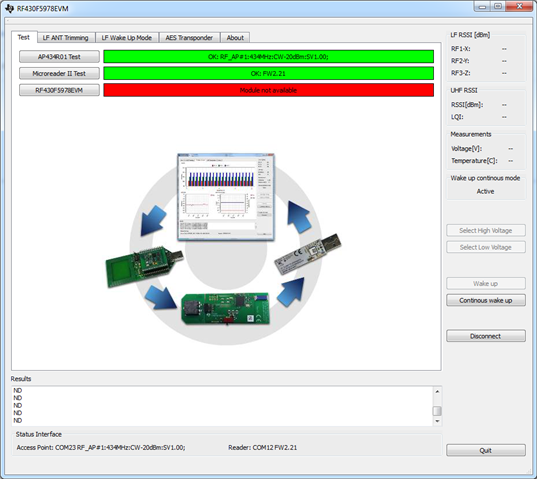
My product is RF430F5978EVM
I installed all the hardware, but it doesn't work.
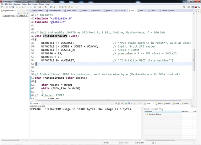
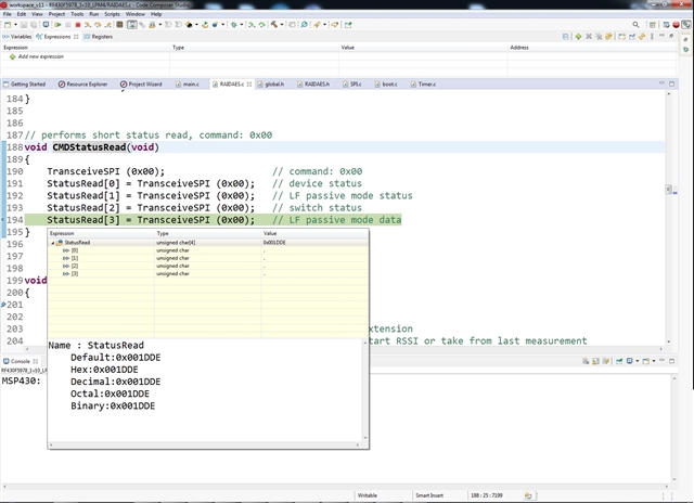
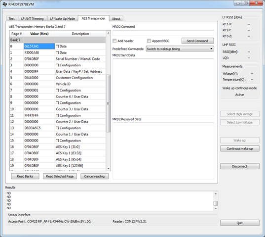
I'm using SPI to check if it's working I'm trying to subtract bank 7 page 2 is the serial number but it's zero.
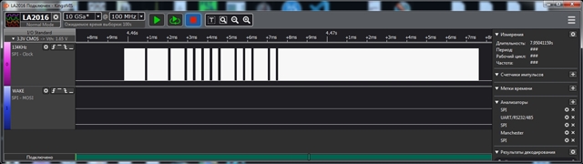
I found out that for every byte sent SOMI = 0
those. after sending command length i see in UCA0RXBUF - 0x00
I can't find the reason why SPI is not working. I also uploaded the original firmware to RF430F5978 but it also does not work.
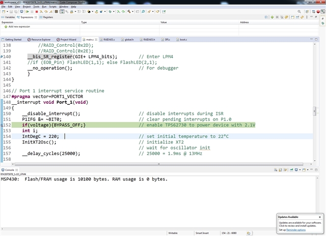
I think the problem is somewhere on the board. I installed a battery, 3V and checked its voltage. I also know about the switch on the board. It is on.
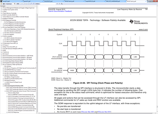
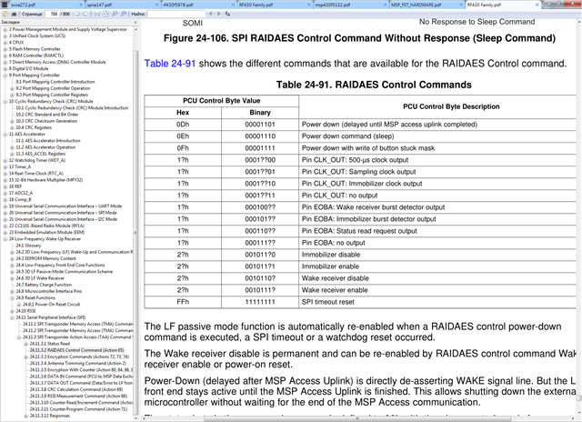
I see that the documentation has a lot of ambiguities, under ?
is it 0 or 1 ?
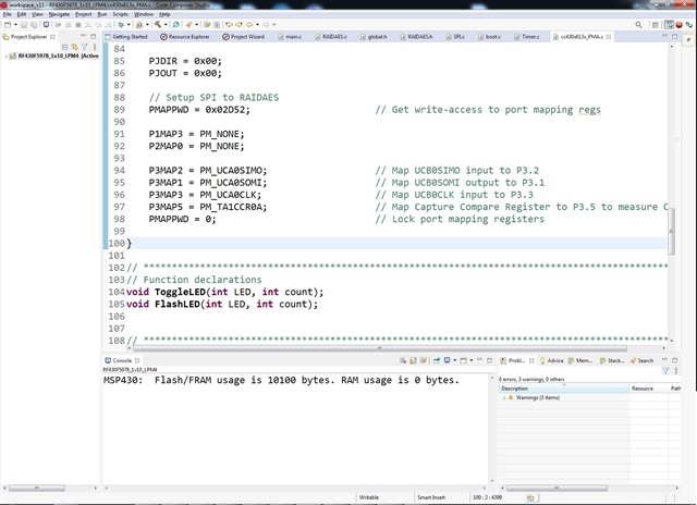
My guess is that the 3D might be misconfigured, but I don't know how to fix it if the SPI is not responding.
There may be a problem with the printed circuit board.
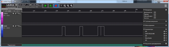
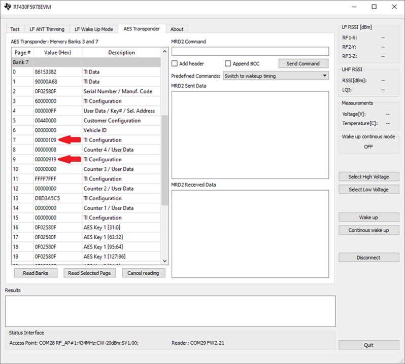
you can see that WAKEA and WAKEB are configured correctly. 9 and 8. but the chip has no response to WAKE
board is not working. And I don't know why this is possible. Please help me find the problem.

Regards,

Danilo

  • Hello Danilo,

    if I understood correctly, your EVM is not responding, your assumption is an issue with the 3D antenna or its frontend configuration, and now you are trying to access the AFE via SPI for debug, which also does not work, right?

    Since you can read bank 7, the LF communication seems to work.

    Since WAKEA and WAKEB are configured correctly, you could try to check the WAKE signal at pin 25 on a WAKE pattern transmission.

    Regarding SPI, the USCI_A0 is mapped to P1.4 ...P1.7 and not to the AFE interconnection. The SPI interconnection is using P3.1 ...P3.3, which does not have a USCI mapped. So I guess the firmware is using a software emulated SPI.

    I can try to check these aspects in the lab b/o next week and provide more details.

    Best regards,

    Andreas.

  • Hi Andreas,

    Thank you for your response. According to our customer,

    To begin with, I will clarify once again that I am still using what is offered on the site as a working option.slrc002
    in this source code
    SPI is used by hardware, UCA and it is configured in the InitPorts() routine
    here is a screenshot of the part where remapping takes place
    see mapping_SPI


    And here is the setting of the SPI itself
    see init_SPI


    I soldered to the WAKE output and used the LA2016 logic analyzer with the software http://www.qdkingst.com
    I am attaching these files for analysis.
    see log.rar

    log.rar
    so WAKE only works on buttons, you can see it in the logs.
    see switch_wake


    And if you start the debugger, then it is stopped in the P1.0 port interrupt, physically connected to WAKE.
    (see switch_wake_debug)


    but as you can see the status is subtracted as zeros.
    see switch_wake_status_read


    With WAKE at 134kHz, you can see the field coming from MDR2, but no WAKE signal.
    see field_wake

    Regards,

    Danilo

  • Hello Danilo,

    yesterday I was able to check your described findings with my setup. Everything was working as expected. I was also able to check the UCA0RXBUF during EVM test and it contained reasonable data. I think your issue is indeed caused by the missing WAKE, because the MCU is not getting activated this way and SPI might not work due to LPM.

    The AES transponder memory seems to be configured correctly from your screenshot, so it is hard to say why you don't see the WAKE.

    Do you have a known good EVM board, which you could compare to?

    Best regards,

    Andreas.

  • Hi Andreas,

    Here is the response of our customer.

    Assumptions about the non-working WAKE, I consider unfounded. After all, as I wrote earlier, WAKE is triggered by a button, ISR is being executed and the status 04 00 01 00 is currently being read
    which confirms the button is pressed.
    Therefore, the WAKE pin itself works, its connection to P1.0 is available on the board.
    but the problem with WAKE remained.
    when I try to issue a command, I see its issuance, but I do not see its opening. But with the help of a debugger with a breakpoint in the interrupt, but on the LED that I light in the interrupt.

    Of course, if I had another module, I would check it too. but I don't have it.

    If you have suspicions that DSTAES is working, tell me how I can check it, given that SPI is now working.

    I found reasons why I didn't see SPI and now I can work with DSTAES from my code.
    But that's where the good news ends.

    First I want to make sure that DSTAES is enabled.
    i send spi RAIDAES
    03 F3 41 2F and read 3 bytes in response 00 F1 41
    next I want the EOB to be connected to the Immobilizer burst detector output
    according to my reasoning, this is team 17
    03 F3 41 17 and read 3 bytes in response 00 F1 41
    As you can see, by status 00, all commands are executed correctly.

    Now I hope to see the EOB change to P4.1
    if (EOB_Pin) {
    P1OUT &= ~BIT1;
    P1OUT |= BIT2;
    }
    else {
    P1OUT &= ~BIT2;
    P1OUT |= BIT1;
    }
    BIT1 - LED1, BIT2 - LED2
    but only one LED is on.

    Regards,

    Danilo

  • Hello Danilo,

    now that the customer found a reason why SPI was not working and obviously fixed it, I wonder if it was board related and if the original firmware would work now. If the RF430F5978EVM GUI would work normal, then this would rule out device and board related issues.

    Best regards,

    Andreas.

  • Hi Andreas,

    We have received this feedback from our customer,

    no, the SPI problems are related to how I did it.
    It was a few mistakes.
    Firstly, I did not install P3SET
    and, accordingly, SPI accessed the default pins
    at the moment I do this before each call to SPI
    P3SEL &=~(BIT3 + BIT2 +BIT1);
    UCA0CTL1 &= ~UCSWRST;
    P3SEL |= 0x0E;
    my second mistake was setting a breakpoint inside the SPI exchange which caused a timeout. Therefore, I incorrectly read the status in the ISR by buttons.

    so the errors were only mine, the code from TI should have run, but it still doesn't run.
    so the problem with WAKE_A remains, DSTAES does not respond to the WAKE pattern.
    I can try to program your file if you give it to me. As I wrote earlier, all attempts to run the source code were unsuccessful.

    Regards,

    Danilo

  • Danilo,

    would it be possible to let the customer read the full content of bank 7? I would like to compare the data against a known working device here in the lab.

    Btw. since the bank 7 readout seems to work for the customer, would it be possible to check the EOB visibility during this operation?

    Best regards,

    Andreas.

  • Danilo,

    today I compared the provided Bank 7 content bit by bit against a known working reference device (see below).
    I found a mismatch in the Wake Pattern A and B (Page 7 and 9), which is mot likely the root-cause for the missing Wake with the RF430F5978EVM GUI.

    I don't think that page 8 is relevant (as there is also a mismatch).

    The rest is matching or is for information only.

    So please let the customer correct page 7 and 9.


    Best regards,
    Andreas.

  • Hi Andreas,

    Please see the response of our customer below.

    Thanks, the change in pages 7 and 9 really helped.
    But I'm still not sure if everything is working correctly.

    When I click the "Wake up" button, I see the field template in the picture.
    And so far everything is correct.
    But now there are buttons that somehow have to switch the voltage either to the battery or to the power converter, but the template for the two buttons is the same.
    In the program, the High / Low Voltage state is generally processed by the buttons on the board.

    And the most important thing is that although I see that the value is transmitted via UFH, the software still thinks that something is not working correctly. When you press the button RF430F5978EVM MDR2 gives the same pattern as for Wake up.

    Perhaps the software version does not match the firmware?
    I continue to understand further, my goal is to create my own teams, and I think there will still be polls.

    Regards,

    Danilo

  • Hi Andreas,

    Our customer added these screenshots.

    1882.Wake.rar

    Regards,

    Danilo

  • Hello Danilo,

    I don't understand what exactly seems not to work from the customers feedback.

    Does the customer mean the buttons in the GUI or the hardware buttons on the board? Anyway they are somehow related.

    The "Select High Voltage" button in the GUI is enabling the Bypass mode of the TPS62730, located on the EVM, which switches to 3V supply. Same can be done with the middle micro-switch on the EVM board. The "Select Low Voltage" button in the GUI is enabling the DC/DC operation TPS62730, which reduces the supply voltage to 2.1V. Same can be done with the left micro switch on the EVM board (see figure 16 in the EVM Users Guide https://www.ti.com/lit/pdf/slru007). This approach is also described in chapter 3.6 of the application note "RF430F5978EVM Optimized Power Consumption" (https://www.ti.com/lit/pdf/slra004).

    Unfortunately the GUI does not provide any feedback on the voltage selection event. But the effect can be observed in the "Voltage [V]" display in the "Measurements" field to the right of the GUI window. The value is getting updated by pressing the "Wake up" button in the GUI. Means, first press "Select High Voltage" button, then the "Wake up" button in the GUI to see the effect.

    Is this answer clarifying the issue or did I misunderstood the issue? If I misunderstood, then please provide more details on the issue observation.

    Best regards,

    Andreas.

  • Hi Andreas,

    Please see the response of our customer below.

    Yes, it's about the problem.
    And the bottom line is that the buttons on the board switch the voltage, and this can be seen on the monitor in the software. But the buttons on the software do not switch this.
    And I'd like to understand why, so I've included diagrams to evaluate it, because both buttons give the same template, which is probably not true.
    Am I assuming that the software version does not match the firmware version or is there another reason why this does not work?

    Regards,

    Danilo

  • Danilo,

    I checked that the software revision and firmware revision are matching the setup, which I used last time and which worked to switch between high and low voltage via software. I also checked the source code of the software and the firmware, that switch between high and low voltage is supported. The only thing, which I had no chance to verify yet, is the difference in LF protocol upon software button click for switch between high and low voltage. I will check next time when I'm in the lab.

    Best regards,

    Andreas.

  • Hi Andreas,

    Thank you very much for the updates. 

    Regards,

    Danilo

  • Danilo,

    today I checked in the lab to compare the LF protocol after pressing the "Select High Voltage" and "Select Low Voltage" buttons in the GUI. I can confirm that it is the same LF protocol for both buttons. The reason for that is that the LF command is just used to wake up the RF430F5978 device in both cases, but the actual voltage switching request is send via UHF. The corresponding code section in the EVM firmware (https://www.ti.com/lit/zip/slrc002) can be found in the file "UHF_control.c", starting at line 338.

    It is hard to say, why the high and low voltage selection is not working for the customer. It was working fine on my setup (which is using the same h/w and s/w revisions).

    As I said before, it is required to first press the "Select High Voltage" followed by pressing "Wake up". Only with the "Wake up" it is getting updated and reflected in the display of the GUI.

    Best regards,

    Andreas.

  • Hi,

    There was no feedback since a while, so I assume this tread is resolved and can be closed. You can still reply to this thread after it is closed, or you can create a new thread.

    Best  Regards,
    Andreas.

  • Hi Andreas,

    I just sent an email to you. Thank you very much for your help.

    Regards,

    Danilo