This thread has been locked.

If you have a related question, please click the "Ask a related question" button in the top right corner. The newly created question will be automatically linked to this question.

TRF7962A: RF issue

Part Number: TRF7962A

Hi team:

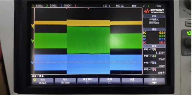
 My customer uses the TRF7962A platform as RFID reader. now the SPI communication part of the chip has been done and the function is normal, and now the RF circuit is being debugged. When I did the label test, the label could not be found, the IRQ status register (0x0C) returned 0x02, and the test RF signal waveform was as follows :

 Yellow is the TRF7962 RX_IN1 pin signal, blue is the RX_IN2 pin signal, and green is the signal at the ANT_OUT point of the antenna transmitter.


Circuit part:

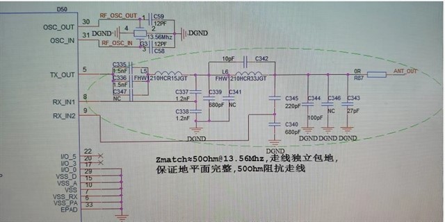
Schematic diagram of the RF part of the core board: ANT_OUT signal is connected to the backplane antenna:

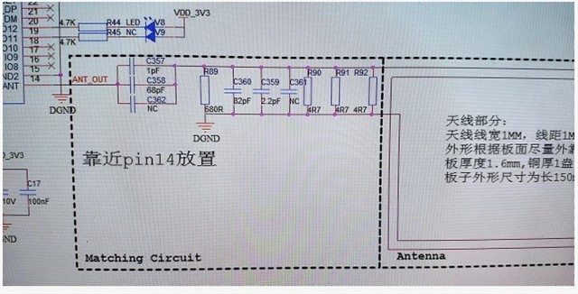
The schematic diagram of the RF part of the mainboard: ANT_OUT is connected to the core board:

would you share any comments or test items that we can check one by one?

Allen Lu

  • Hello Allen,

    the schematic is pretty much the same as the TI reference design, except R90, R91 and R92 close to the Antenna. Are these resistors really assembled or NC? If these resistors are assembled then this almost like an antenna shortage, and this might be the root cause for the malfunction.

    In general antenna matching is important, and since the matching network and the antenna trimming circuitry were copied from reference design, it would be important that the antenna parameter (especially L and Q) are also matching the reference antenna. If this is not given, then the antenna requires tuning as explained in the Antenna Design Guide.

    The matching circuitry between the TRF device and the ANT_OUT is intended to match from IC output impedance to 50 Ohm. The trimming circuit between ANT_OUT and antenna is intended to match from 50 Ohm to the antenna impedance. Therefore ANT_OUT is a controlled 50 Ohm test point, and if removing the 0 Ohm resistor (R87) then it would be possible to measure in both directions independently. So you could confirm TX power from the IC direction at this point, and antenna matching in the other direction.

    Please be informed that I will be out of office until Apr. 25. Good luck with the antenna matching in the meantime.

    Best regards,

    Andreas.

  • Hi,

    There was no feedback since a while, so I assume this tread is resolved and can be closed. You can still reply to this thread after it is closed, or you can create a new thread.

    Best  Regards,
    Andreas.