This thread has been locked.

If you have a related question, please click the "Ask a related question" button in the top right corner. The newly created question will be automatically linked to this question.

RF430FRL152HEVM: NDEF Message Exchange Time Constraint Issue

Part Number: RF430FRL152HEVM
Other Parts Discussed in Thread: TRF7970A, , MSP430F2370, DLP-7970ABP

Hi team ,

i am using msp430f5529lp and trf7970a with RF430FRL152HEVM for sending ndef message from RF430FRL152HEVM to trf7970a.

since i am following the basic example given in "RF430FRL15xH NFC Projects" folder ,the example works fine but my requirement is sending the ndef message by turning on RF signal only for one milliseconds.

Any Suggestions are appreciated.

Thanks 

Shivraj 

  • Hello Shivraj,

    sorry for the delayed response. I was out of office last week and unfortunately I'm busy for the next 3 days. I will look at your request after that.

    Best regards,

    Andreas.

  • Hello Shivraj,

    I think it is not possible to transmit an NDEF message with the RF430FRL152HEVM in 1ms, because of the ISO15693 standard, which uses 26.48kbps max. In 1ms you would be able to transmit 26 bit in 1ms (not considering protocol overhead). This is not enough for an NDEF message. Even with ISO14443B at 424kbps (different tag) it might be a challenge.

    Best regards,

    Andreas.

  • HI ,

    Thanks for the reply, and i have some other queries .

    Is it possible to  receive 4 byte of data  within one millisecond  by sending read command from trf7970a to trf7970a.(i.e transreceiving within one millisecond)

  • HI ,

    is there any method where we can find out the how much of bytes transferred from trf7970a to tr7970a  in a given time duration.


    Thanks

    shivraj

  • Hello Shivraj,

    sending data from one TRF7970 to another would be the use case of Peer-to-Peer mode. This mode requires implementation of an anti collision algorithm, which ads quite some overhead.

    Alternatively the TRF7970A can also operate in card emulation mode, and receiving data from another TRF7970A in Reader/Writer mode, if this fits to your application. This would emulate a reader to tag connection. Here the ISO Write commands can provide a more direct and time efficient data transfer. Here I would recommend to study the ISO specifications for the timings, command formats and protocol overhead.

    For timing analysis it would be possible to "sniff" the RF of the TRF7970A with an extra loop antenna. You could see at least the AM modulation of the RF and analyze the bits.

    Best regards,

    Andreas.

  • Hi ,

    Thanks for the reply and i have another doubt 

    What happens if i switch off the RF Field ? will it be enter into discovery mode(i,e, start from SENSE_REQ)or will it be in pause state?.

  • Hello Shivraj,

    could you please explain your question a bit more detailed? Which mode and scenario are you referring to?

    Best regards,

    Andreas.

  • Hi 

    i am using P2P communication for sending and receiving data in one millisecond duration , but my requirement is need to transmit and receive data in one millisecond duration and  for 9 millisecond duration i am switching off the  RF Field  what will happen during the 9 millisecond duration will it be enter into discovery mode(i,e, start from SENSE_REQ)or will it be in the previous state ?

  • Hello Shivraj,

    it depends on the role of the device. You can look up the communication flow diagrams in the application note "NFC active and passive peer-to-peer communication using the TRF7970A (Rev. B)".

    Best regards,

    Andreas.

  • Hi  , I checked with the "NFC active and passive peer-to-peer communication using the TRF7970A (Rev. B)" but i didn't got any clue or hint regarding OFF and ON Rf Field, since i am trying on time critical application i want to switch off the rf field for 9millisecond duration and 1 millisecond duration i want to transmit and receive the data.

    I Need clarification for the question:

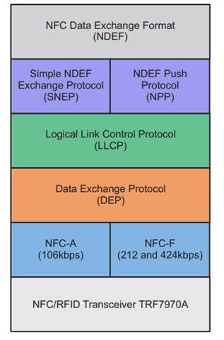
    in the above diagram if i switch off the RF field after NFC-A will the TRF module RESET to start from Beginning or else  will be at NFC-A.

    if the module will reset if we switch off the RF Field means need to change the module .

    since i checked in the "TRF7970A Multiprotocol Fully Integrated 13.56-MHz RFID and Near Field Communication
    (NFC) Transceiver IC" data sheet in page number 14:

    its stated that 

    Based on the first command from the INITIATOR, the following actions are taken:
    • If the first command is SENS_REQ or ALL_REQ, the TARGET must enter the SDD protocol for 106-
    kbps passive communication to begin; afterward, the baud rate can be changed to 212 kbps or 424
    kbps, which is determined by the NFC initiator device. If bit B5 in the NFC Target Detection Level
    register is not set, the MCU handles the SDD and the command received is send to FIFO. For
    interoperability purposes, TI recommends allowing the MCU to handle the SDD process rather than
    use the TRF7970A Auto-SDD feature to ensure interoperability with other NFC devices. "If the RF field
    is turned off (B7 in NFC Target Protocol register is low) at any time, the system sends an IRQ to the
    MCU with bit B2 (RF field change) in the IRQ register set high. This informs the MCU that the
    procedure was aborted and the system must be reset. The clock extractor is automatically activated in
    this mode".

    Please provide the clarification for  this statement  "If the RF field
    is turned off (B7 in NFC Target Protocol register is low) at any time, the system sends an IRQ to the
    MCU with bit B2 (RF field change) in the IRQ register set high. This informs the MCU that the
    procedure was aborted and the system must be reset. The clock extractor is automatically activated in
    this mode".

    As per the above statement if we switch off the RF Field will the entire module will be reset or any other meaning please help me in understanding this.

  • Hi Andreas Mueller,

    Since i am using TRF7970A with MSP430F5529LP i want to implement Direct Mode 

    "https://www.ti.com/lit/an/sloa214/sloa214.pdf?ts=1652782634825&ref_url=https%253A%252F%252Fwww.google.com%252F"

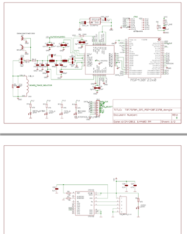
    The above mentioned link is for MSP430F2370 implementation and below is the reference pinout diagrams 

    I tried to port from MSP430F2370 to MSP430F5529LP but not able to implement the Direct mode since there are no pin available so please help us in implementing the Direct mode using TRF7970A+MSP430F5529LP

    Thanks,

    Shivaraj 

  • Hello Shivraj,

    are you using the DLP-7970ABP?

    Best regards,

    Andreas.

  • Hello Shivraj,

    the simplified schematic of the DLP-7970ABP can be found on the web page of the third party vendor DLP-Design (https://www.dlpdesign.com/bpd/7970ABPv47.pdf).

    As you can see, the MOD pin signal can be accessed at R12 of the DLP-7970ABP. If you remove R12 you can blue-wire MOD to some unused Launchpad port pin. The MISO pin is anyway connected to the Launchpad for SPI control.

    Best regards,

    Andreas.