This thread has been locked.

If you have a related question, please click the "Ask a related question" button in the top right corner. The newly created question will be automatically linked to this question.

Layout TRF7960 RFID module

Other Parts Discussed in Thread: TRF7960

Hello!

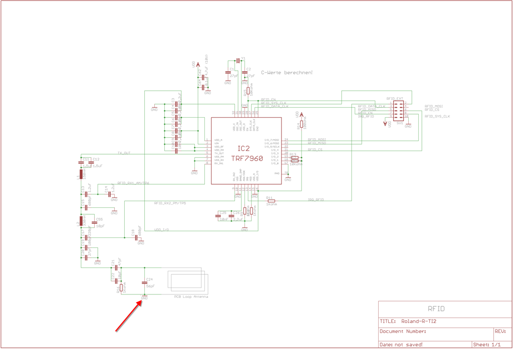
We are currently working on a board extension for a test platform in our lab. We want to extend it with RFID capabilities based on TRF7960. To match design constrains we had to deviate from the reference design.

Could you take a look at the provided layout and comment? I hope that I have not overlooked anything critical. For example should the ground planes be extended?

Thank you very much!
Daniel

(left = top, right = bottom)


  • Hi Daniel,

    Could you provide a higher resolution image?  Please provide your schematic as well.

    Also, what are the dimensions of the antenna coil?    

  • Hi Eddie,

    I have updated the pictures in the post above and added the schematic. It should be identical to the reference design as in the TRF7960EVM, just without the uC and USB-serial IC. Exact dimensions of the coil are 1.6275" x 2.2325" (41.34 mm x 56.77 mm) from the top left to the top right corner. Trace width is 0.05" (1.27 mm) with a trace-to-trace distance of 0.07" (1.78 mm). I hope that helps!

    Thank you for your time!
    Daniel

  • Hi Daniel,

    Thanks for the images... This is much easier to see now!

    First, check your values for C11, C12, C13, and C14.  1500pF does not equal 1.5uF. 

    Be sure that you ground your PCB coil antenna.  It looks like you have this correct in your layout, but not on the schematic.

    I am not sure what is the purpose of R14.  I/O_1 and I/O_2 are supplied by VDD_X.  You should remove R14 and the connection to VDD. 

    The layout looks okay.  Based on the dimensions of your antenna coil, I calculate this should provide about 1.79uH inductance in free space.  You should be able to tune this.  I recommend looking at the TRF7960TB antenna tuning section for some information on this process if you have not already seen this.

    TRF7960TB Users Guide: http://focus.ti.com/lit/ug/slou297/slou297.pdf


  • Eddie LaCost said:

    First, check your values for C11, C12, C13, and C14.  1500pF does not equal 1.5uF.


    Yes, that would have been nasty! Thank you!

    I am however not sure what you mean with:

    Eddie LaCost said:

    Be sure that you ground your PCB coil antenna.  It looks like you have this correct in your layout, but not on the schematic.

    You have been very helpful so far. Thank you, Eddie!

    Regards,
    Daniel

  • Daniel,

    You must have ground on one side of your antenna coil.  See the attached clarification on the schematic.

  • Thank you! Now I am with you again. Yes, this ground connection has been added in the layout, but you are right it makes sense to add this in the schematic as well.

    Regards,

    Daniel