This thread has been locked.

If you have a related question, please click the "Ask a related question" button in the top right corner. The newly created question will be automatically linked to this question.

TRF7964A: TRF7964A

Part Number: TRF7964A
Other Parts Discussed in Thread: DLP-7970ABP, MSP-EXP430G2ET

Hi Andrea, 

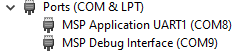
I able to successfully run the code from the TRF7970ABP_RFID_Reader_Demo using the Booster pack and the Launch Kit. The correct LED blinks when I use a 14443 Type A Tag.

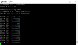
However, when using debug mode, after the LED blinks, I see that in the function NFC_appIso14443a(), when I get here:

if (ISO14443A_getType4ACompliance() == true)
{
NFC_appIso14443aType4NDEF(); // For a Type 4A compliant tag, the tag is put into Layer 4, and in order to attempt to read/write NDEF contents
}
else
{
NFC_appIso14443aType2(0x10); // If a tag that is not Type 4A compliant then assume it is NFC Type 2. Proceed to read data block(s)
}

I enter into NFC_appIso14443aType2() and then function iISO14443A_sendT2TReadFourBlocks() returns FAIL.

I do not know if my tag is Type 4 or Type 2. 

Why does the LED blink before the type 4/2 is checked? Does this mean that this check isn't neccessary?

Thank you for your help, 

Becky

  • Hello Becky,

    sorry for the late reply, but the support bandwidth is very limited at this time.

    In this example the LED is purposed as an ISO14443A indicator. Both tags, Type 4 and Type 2 are using ISO14443A (see figure 2 in application note "NFC/HF RFID reader/writer using the TRF7970A").

    You can visualize more information about your tag with the help of the UART output of the TRF7970ABP_RFID_Reader_Demo (see below).

    Alternatively you could check your tag with a smartphone, for example by using the NFC Tools app.

    Let me know if you have further questions.

    Best regards,

    Andreas.

  • Hello Andreas, 

    I assume I cannot use the UART when I am debugging, as it is the same connection. 

    But when I am not debugging, I am still not able to get output on the UART. Can you please tell me how to config - baud rate, stop bits, etc?

    Thanks, 

    Becky

  • Also, I need to re-install the workspace that we created in our call in September.

    Can you please give me instructions?

    Thanks, 

    Becky

  • Hello Becky,

    it is possible to use the UART while debugging, because they are using different COM ports. You can see it in the Windows Device Manager.

    Although the description in the header of main.c in the TRF7970ABP_RFID_Reader_Demo example is saying 115200 Baud, you should use 9600 Baud. I think this is a limitation of the older Launchpads. So the serial connection settings should be 9600 Baud, 8 data bits, 1 stop bit, no parity, no flow control.

    For re-creating the CCS workspace you can delete the entire folder content inside workspace_v10. Then download and unzip the example project (http://www.ti.com/lit/zip/sloc297). Then start CCS. In the menu select "Project" - "Import CCS Projects...". In the "Select search-directory" field browse for the location of your unzipped example code (...\sloc297c\TRF7970ABP_RFID_Reader_Demo) and press "Select Folder". Now I would recommend to check-mark "Copy projects into workspace" (at the bottom of the window) and hit "Finish". Now you can build the project with the hammer symbol and start a debug session with the bug symbol.

    Let me know if you have any questions.

    Best regards,

    Andreas.

  • Hi Andreas , 

    Thank you, I was able to successfully reload and run the project.

     Then I noticed this regarding the UART:

    //===============================================================

    // Toggle UART Host Communication functionality

    // TODO: Hardware modification to the default shipped board is required for UART:
    // Take the two jumpers for the "TXD" and "RXD" pins and connect them horizontally
    // instead of vertically. When done correctly, this should connect the pins which
    // are labelled "TXD" and "RXD" pins which are on the MSP-EXP430G2 side of the
    // board to each other. The two pins above them on the "Emulation" side of the
    // board should also be tied together horizontally.

    After changing the jumpers, everything is ok.

    That is all for now.

    Thank you!

    Becky

  • Hi Andreas, 

    I have another question. On the evaluation board, are there free pins with access that I can use to do realtime testing? I want to attach oscilloscope probes to look at the timing.

    Thanks, 

    Becky

  • Hi Becky,

    thanks for your feedback.

    Here are the links to the DLP-7970ABP datasheet and schematics (third party vendor DLP Design).

    http://www.dlpdesign.com/rf/dlp-7970abp-ds-v14.pdf

    https://www.dlpdesign.com/bpd/7970ABPv47.pdf

    I think module pins 2...6 are unused by the DLP-7970ABP board, otherwise you could also repurpose the LED pins for routing your debug signals.

    The schematic of the MSP-EXP430G2ET can be found in chapter 6 of the MSP-EXP430G2ET users guide.

    Let me know if you have any questions.

    Best regards,

    Andreas.