


Other Parts Discussed in Thread: MSP430F2370, MSP-EXP430G2ET
Hi,
I have a project board based on msp430f2370 and TRF7970A. I'm modifying the sloc297 code which is for MSP430G2553 to work with msp430f2370.
Want to know if I have to take care of anything in particular while porting code ?
When I ran the simulation after making the configuration changes, the program got stuck.
The program loops at the red box.
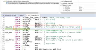
Main code code stuck VLO calibration.
-
My main function is as follows
void main(void)
{
uint8_t ui8VLOCalibCount;
// TODO: Remove LED2 Jumper on G2 LaunchPad if using it, otherwise SPI will not work.
// Stop the Watchdog timer,
WDTCTL = WDTPW + WDTHOLD;
// Select DCO to be 8 MHz
MCU_initClock();
MCU_delayMillisecond(10);
// Calibrate VLO
MCU_calculateVLOFreq();
// Set the SPI SS high
SLAVE_SELECT_PORT_SET;
SLAVE_SELECT_HIGH;
// Four millisecond delay between bringing SS high and then EN high per TRF7970A Datasheet
MCU_delayMillisecond(4);
// Set TRF Enable Pin high
TRF_ENABLE_SET;
TRF_ENABLE;
// Wait until TRF system clock started
MCU_delayMillisecond(5);
// Set up TRF initial settings
TRF79xxA_initialSettings();
TRF79xxA_setTrfPowerSetting(TRF79xxA_3V_FULL_POWER);
#ifdef ENABLE_HOST
// Set up UART
UART_setup();
#endif
// Initialize all enabled technology layers
NFC_init();
// Enable global interrupts
__bis_SR_register(GIE);
// Enable IRQ Pin
IRQ_ON;
#ifdef ENABLE_HOST
UART_putIntroReaderMsg(RFID_READER_FW_VERSION, RFID_READER_FW_DATE);
#endif
while(1)
{
// Poll for NFC tags
NFC_findTag();
// VLO随温度和时间的推移而漂移,因此必须定期重新校准每隔25次NFC轮询程序校准VLO
// VLO drifts with temperature and over time, so it must be periodically recalibrated
// Calibrate the VLO every 25 passes of the NFC polling routine
ui8VLOCalibCount++;
if (ui8VLOCalibCount == 25)
{
// Calibrate VLO
MCU_calculateVLOFreq();
// Reset Calibration Counter
ui8VLOCalibCount = 0;
}
}
}
-
The source code for my VLO calibration is as follows
.cdecls C,LIST, "msp430f2370.h"
;Functions
.def TI_measureVLO
;Variables
.bss TI_8MHz_Counts_Per_VLO_Clock, 2
.align 2
.text
;DEVICE_TYPE .set 2 ; 2xx devices with a Timer_A3
DEVICE_TYPE .set 3 ; 2xx devices with a Timer_A2
.if DEVICE_TYPE = 3 ; For Timer_A2 devices
TACCTLX .set TACCTL0
TACCRX .set TACCR0
.else
TACCTLX .set TACCTL2
TACCRX .set TACCR2
.endif
;-------------------------------------------------------------------------------
TI_measureVLO
; returns: r12
; -An int representing the number of 8MHz clock pulses in one VLO cycle
; -This value is identical to the number put into TI_8MHz_Counts_Per_VLO_Clock
;-------------------------------------------------------------------------------
mov.b &BCSCTL1, r15 ; preserve previous settings
mov.b &DCOCTL, r14
push.b &BCSCTL2
push.b &BCSCTL3
push.b &P2SEL
bic.b #0xC0, &P2SEL ; clear P2SEL bits to avoid XTAL interference.
mov.b &CALDCO_1MHZ, &BCSCTL1 ; Set range
mov.b &CALDCO_1MHZ, &DCOCTL ; Set DCO step + modulation
mov.w #CM_1+CCIS_1+CAP,&TACCTLX ; CAP, ACLK
mov.w #TASSEL_2+MC_2+TACLR, &TACTL; SMCLK, cont-mode, clear
mov.b #LFXT1S_2, &BCSCTL3 ; ACLK = VLO
clr.b &BCSCTL2
bis.b #DIVA_3, &BCSCTL1 ; ACLK=VLO/8
bic.w #CCIFG, &TACCTLX ; Clear capture flag
edge_one bit.w #CCIFG, &TACCTLX ; Test capture flag to skip first signal
jz edge_one
bic.w #CCIFG, &TACCTLX ; Clear capture flag
edge_two bit.w #CCIFG, &TACCTLX ; Test capture flag to skip second signal
jz edge_two ;
mov.w &TACCRX, r13 ; save hardware captured value
bic.w #CCIFG, &TACCTLX ; Clear capture flag
edge_three bit.w #CCIFG, &TACCTLX ; Test capture flag to capture a good clock
jz edge_three ;
bic.w #MC_3, &TACTL ; stop timer
mov.w &TACCRX, r12
sub.w r13, r12
mov.w r12, &TI_8MHz_Counts_Per_VLO_Clock
mov.b r15, &BCSCTL1
mov.b r14, &DCOCTL
pop.b &P2SEL
pop.b &BCSCTL3
pop.b &BCSCTL2
ret
.end
