- Ask a related questionWhat is a related question?A related question is a question created from another question. When the related question is created, it will be automatically linked to the original question.
This thread has been locked.
If you have a related question, please click the "Ask a related question" button in the top right corner. The newly created question will be automatically linked to this question.
Tool/software:
Hi Expert,
we need advice for how to apply a Japan technical standard compliance, Japanese FCC.
Refer to TRF7970A datasheet 7.1.2 Schematic
https://www.ti.com/lit/ds/symlink/trf7970a.pdf
TRF7970 is used to read and write RF-ID (ISO15693).
(Tag:RF-HDT-DVBB)
In Japan standard, if the output level is 500uV/m or higher, it is necessary to apply to the Ministry of Internal Affairs and Communications,
and at that time, it is necessary to use the PN 9 stage pseudo-random signal as the modulation signal.
The TRF7970 itself does not have a pseudo-random signal in the PN9 stage, and modulation by the PN9 stage pseudo-random signal in the IC alone cannot be applied.
Please explain how to modulate by inputting a pseudo-random signal of the PN 9 stage from an external source.
The PN 9 stage pseudo-random signal is generated and input by the CPU.
We eed advice the circuit configuration and register settings of TRF7970.
Hi,
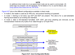
I have no experience with PN modulation but I think you can use the Direct Mode to control the AFE. See below references on the datasheet. Please refer to the datasheet for details. This app note about Direct Mode will be also useful. Using Special Direct Mode With the TRF7970A
The TRF7970A device supports data rates up to 848 kbps with all framing and synchronization tasks for
the ISO protocols onboard. The TRF7970A device also supports reader and writer mode for NFC Forum
tag types 1, 2, 3, 4, and 5. Other standards and even custom protocols can be implemented by using one
of the direct modes the device offers. These direct modes let the user fully control the AFE and also gain
access to the raw subcarrier data or the unframed, but already ISO-formatted, data and the associated
(extracted) clock signal.

External control of the transmit modulation depth is possible by setting the ISO Control register (0x01) to
direct mode. While operating the TRF7970A in direct mode, the transmit modulation is made possible by
selecting the modulation type ASK or OOK at pin 12. External control of the modulation type is made
possible only if enabled by setting B6 in the Modulator and SYS_CLK Control register (0x09) to 1.

6.10.6 Direct Mode
Direct mode allows the user to configure the reader in one of two ways. Direct mode 0 (bit 6 = 0, as
defined in ISO Control register) allows the user to use only the front-end functions of the reader,
bypassing the protocol implementation in the reader. For transmit functions, the user has direct access to
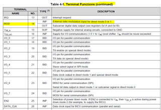
the transmit modulator through the MOD pin (pin 14). On the receive side, the user has direct access to
the subcarrier signal (digitized RF envelope signal) on I/O_6 (pin 23).
Direct mode 1 (bit 6 = 1, as defined in ISO Control register) uses the subcarrier signal decoder of the
selected protocol (as defined in ISO Control register). This means that the receive output is not the
subcarrier signal but the decoded serial bit stream and bit clock signals. The serial data is available on
I/O_6 (pin 23) and the bit clock is available on I/O_5 (pin 22). The transmit side is identical; the user has
direct control over the RF modulation through the MOD input. This mode is provided so that the user can
implement a protocol that has the same bit coding as one of the protocols implemented in the reader, but
needs a different framing format