Other Parts Discussed in Thread: ENERGYTRACE
Tool/software:
Hi,
At first, my toolchain are following.
- SDK: SIMPLELINK-LOWPOWER-F3-SDK (version. 8.10.01.02)
- Examples: examples\rtos\LP_EM_CC2340R5\prop_rf\rfPacketTx
- Compilar: ARM CGT CLANG 4.0.0
- IDE: CCS 12.8
I want to measure the idle current to check whether it is same as the data sheet.
So I added LGPT function to empty.c in SDK examples.
void *mainThread(void *arg0)
{
/* 1 second delay */
uint32_t time = 1;
/* Call driver init functions */
GPIO_init();
/* Configure the LED pin */
GPIO_setConfig(CONFIG_GPIO_LED_0, GPIO_CFG_OUT_STD | GPIO_CFG_OUT_LOW);
/* LGPT setting&start for idle current measurement */
uint32_t counterTarget;
LGPTimerLPF3_Handle hTimer;
hTimer = NULL;
LGPTimerLPF3_Params params;
LGPTimerLPF3_Params_init(¶ms);
params.hwiCallbackFxn = timerCallback;
params.prescalerDiv = 10;
hTimer = LGPTimerLPF3_open(CONFIG_LGPTIMER_0, ¶ms);
if(hTimer == NULL) {
//Log_error0("Failed to open LGPTimer");
//Task_exit();
}
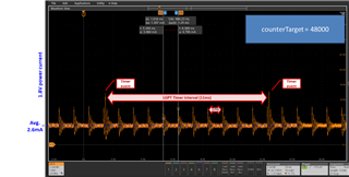
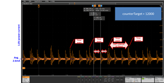
counterTarget = 48000; //1ms with a system clock of 48 MHz
LGPTimerLPF3_setInitialCounterTarget(hTimer, counterTarget, true);
LGPTimerLPF3_enableInterrupt(hTimer, LGPTimerLPF3_INT_TGT);
LGPTimerLPF3_start(hTimer, LGPTimerLPF3_CTL_MODE_UP_PER);
/* Turn on user LED */
GPIO_write(CONFIG_GPIO_LED_0, CONFIG_GPIO_LED_ON);
while (1)
{
sleep(time);
GPIO_toggle(CONFIG_GPIO_LED_0);
}
}
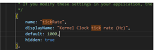
The settings for Power Policy, DCDC and LF clock are as follows.
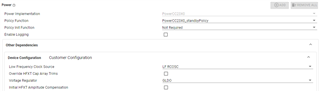
The LP_EM_CC2340R5 is supplied with a power supply voltage of 1.8V.
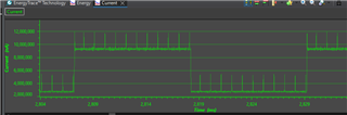
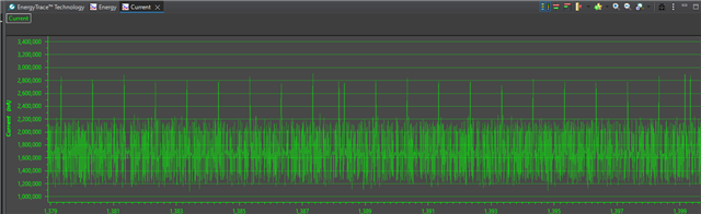
A snapshot of waveform that I measured power supply current is following.
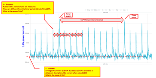
I set the timer cycle of the LGPT to 11msec, so I expected to measure an idle current of 1.5mA except when the LGPT was triggered, but that was not the case.
I would like to know the cause of this. This is 1st Problem.
In addition, a pulse waveform was measured at a cycle of 1ms.
I would also like to know the cause of this. This is 2nd Problem.
Best regards,