This thread has been locked.

If you have a related question, please click the "Ask a related question" button in the top right corner. The newly created question will be automatically linked to this question.

TMS3705: Electromagnetic Interference Issues with TMS3705 and UCC27424

Part Number: TMS3705

Tool/software:

Hello! I hope this message finds you well.

We are currently facing a technical issue in a project and would like to request your support, in case you have dealt with a similar situation with any customer.

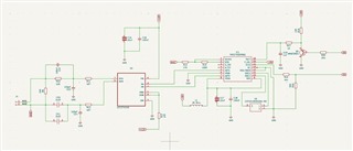
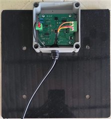
We have developed an RFID reader circuit for animal identification, operating at a frequency of 134.2 kHz, using the TMS3705 transponder. The current average reading range is approximately 20 cm. The circuit consists of the following blocks:

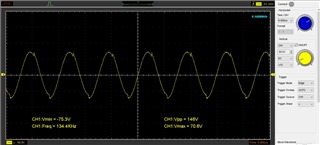
Reading antenna: 220uH Q 21 (dimensions 240 x 240mm) with 2 resonant capacitors of 3.3nF in parallel = 6.6nF, tuned to 134.2 kHz;

Power driver (UCC27424D), responsible for amplifying the signal generated by the TMS3705 and applying it to the antenna;

TMS3705 IC, which performs modulation/demodulation and RFID system control;

Ceramic oscillator (CSTCR4M00G53A-R0), 4 MHz, used as the clock source for the TMS3705;

ATmega328P microcontroller, which interfaces with the TMS3705 (sending and receiving serial data).

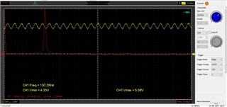
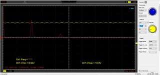
The circuit is powered by a 12 V switching power supply, and the problem arises when electric motors driven by frequency inverters are operating on the same power grid (even if physically distant). In these cases, the transponder's reading range is significantly reduced.

To mitigate this interference, we have already implemented the following measures:

Installation of a passive EMI filter at the power supply input;

Installation of a passive EMI filter at the switching power supply output;

Use of an isolated DC-DC converter from the 12 V output;

Use of shielded cables between the circuit and the reading antenna.

Despite these actions, the issue persists. We have observed a slight improvement in range when using the DC-DC converter, which we believe is due to an additional ground path. In fact, touching the circuit’s GND terminal with a finger also improves the range considerably, which reinforces the electromagnetic interference hypothesis.

At this point, we are out of clear alternatives to solve the issue, and we would like to know if your technical team has any additional recommendations or if you have encountered similar cases in the field.

We look forward to any guidance or suggestions that might help us. Thank you in advance for your attention and support.

  • Hello Vinicius, 

    Firstly, what kind of antenna are you using? Additionally, have you tested the circuit when connected to a battery pack of some kind, or to power that is not on the same grid as the electric motors? 

    How large is the ground plane on your PCB, is it the entire back side of the PCB? 

    Please let me know, and I hope to have a solution for you by the end of this week (04/11). 

    Thanks,

    Isaac

  • Hi Isaac,

    Thank you for your response.

    Yes, we tested on another network without interference, and the range returned to normal.

    We used a hand-wound square antenna with dimensions of 240 x 240 mm, made with AWG30 copper wire, 220uH, Q factor of 21.
    There is a ground plane across the entire front of the board, measuring 80 x 70 mm.

    On the bottom side of the board, there is a disconnected mesh.

    We also tested with a board that has no ground plane, and the same issue occurred.
    Additionally, we tried several types of switching power supplies, including those from PCs and laptops, but were unsuccessful.

  • Hello Vinicius, 

    I apologize for the delay. I will be working with a hardware engineer on the team to look at the schematic provided. I will mention, we typically see loop or ferrite stick antennas used for this IC. 

    So, you tried a power supply from a PC, and you still saw the issue? I assume the PC is connected to the same power grid as the electric motors? 

    Thanks, 

    Isaac

  • Hello Vinicius, 

    A few things: 

    1. Have you done any analysis of the resonant frequency of the noise on the power line? If so, you will need to size your bypass capacitors to filter out this frequency. This should help with the performance. 

    2. A ferrite bead can be used to block specific frequencies like bypass capacitors, again, you will need to know the frequency of the noise. 

    3. Please look into section 8.1, and 8.3 of the datasheet. These will provide the absolute maximum and the recommended operating values. You will need to keep the device between 4.5 and 5.5v to maintain recommended operating ranges. 

    Thanks,

    Isaac

  • Hello Isaac,

    Thank you for your response.

    Yes, the PC power supply was connected to the same power grid as the electric motors, which likely exposed it to the same electromagnetic interference (EMI). Even with the PC power supply, the issue persisted, suggesting that the noise from the motors is strong enough to disrupt the system despite using a different power source on the same grid.

    We carried out an analysis of the power line with and without the motors running, using the FFT (Fast Fourier Transform) function of the oscilloscope. In both scenarios, the observed signal remained unchanged, showing a 60 Hz resonance with no significant harmonics present.

    We also measured the antenna's resonance frequency, and the results remained consistent, with a reading of approximately 134 kHz and a variation of ±1 kHz, as observed on the oscilloscope.

    The bypass capacitors (C13 and C14) used have a nominal value of 220 pF. Since no high-frequency noise could be detected, we performed empirical tests by replacing these capacitors with others of different values (1 nF and 15 pF) to check for any impact on circuit behavior. However, no noticeable effect was observed.

    The operational parameters of the TMS3705 are in accordance with the datasheet specifications.

    Additionally, we replaced the inductor at the TMS3705 power input with another one using a ferrite core, but this change also did not result in any improvement.

    The attached images show the frequency analysis of the power line and antenna as captured by the oscilloscope.

  • Hello Vinicius, 

    Can you capture a scope view of the 5v and 12v supply on the board? If there is noise entering the PCB from the power supply, it will be visible here. 

    Additionally, how physically close is the motor from the device? Is it possible the problem is caused by radiated noise vs power supply noise? Can you try covering the IC with a RF shield? 

    Also, the power supply waveform looks very clean from what I can tell. Are you sure this is what is causing the degradation of the RX/TX distance? 

    I apologize for the delay in response. Let me know. 

    Thanks,
    Isaac

  • Hello Isaac,

    Thank you for your response.

    We conducted an analysis using an oscilloscope at the power input of the board, both under normal conditions and in the presence of disturbances in the power grid. In both scenarios, the signal behavior remains the same: it is a clean signal. To observe any significant variation, it is necessary to set the oscilloscope to a highly sensitive scale, which is expected in this type of measurement. This variation is consistent in both situations.
    The physical distance between the antenna and the motor is approximately 30 meters. However, the antenna operates normally when the power grid is stable, which makes the hypothesis of radiated noise being the cause of the issue unlikely.
    Based on the observed evidence, our current hypothesis is that the problem is related to noise in the power supply. This is due to the fact that, in the absence of disturbances in the grid, the system operates normally, while in the presence of disturbances, a degradation in the antenna's reading range is noticeable.
    Attached are screenshots showing the signal on the 5V and 10V power rails under electrical noise. An intermittent oscillation can be observed on these rails, possibly due to the electronic board being placed over the inductive antenna.

    Thanks, 

    Vinicius

  • Dear Isaac,

    Good morning. I hope this message finds you well.

    Do you have any further guidance or recommendations that could help us solve our problem? We would greatly appreciate your support.

    Thank you in advance. I look forward to your response.

    Best regards,

  • Hello Vinicius, 

    From the oscilloscope views provided, I believe that fully narrows down the problem to the motor. The 130kHz noise is concerning considering the transmitted frequency is 134.2 kHz. 

    My recommendation would be to add an additional filter to the power rails to filter out that frequency noise. This may be beneficial for all of your boards to prevent this problem on other devices as well. 

    Besides for this, the problem seen is not a problem with the TMS3705 device. We cannot confirm proper functionality if the power rail contains noise, especially when the noise is around 134.2kHz. 

    Thanks, 
    Isaac

  • Hi Isaac,

    Thank you very much for your support and detailed analysis.

    We appreciate the confirmation that the issue is not related to the TMS3705 device. Based on your observations, we will explore new alternatives, including adding an additional filter to the power rails to mitigate the noise around 130kHz.

    This action may indeed benefit all of our boards and help prevent similar issues in the future.

    Thanks again for your assistance — we’ll continue working toward the best solution.

    Best regards,
    Vinicius