This thread has been locked.

If you have a related question, please click the "Ask a related question" button in the top right corner. The newly created question will be automatically linked to this question.

CC2652RSIP: Achievable RF output level

Part Number: CC2652RSIP
Other Parts Discussed in Thread: LP-CC2652PSIP

Tool/software:

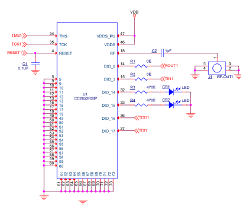
We are using the device CC2652RSIP  in our application.

We are getting +3 dBm o/p. At RF o/p of the device we connected  1 pf capacitor and SMA connector.

The following is the circuit we used. Whether we can achieve better level than +3dBm.

please suggest. If possible, please share RF circuit design guidelines to be followed for

the device CC2652RSIP and CC2651RSIPA

Thank you.

  • Hi,

    Since the output power is something very dependent on the physical aspects of the system, I can make a few comments and provide some references.

    The first aspect I would check is the method of measurement - if you are doing conducted measurements, make sure you are using a calibrated Spectrum Analyzer and is accounting for losses on the cables and connectors from the device to the instrument. Also check the Spectrum Analyzer settings (RBW and VBW, detector type, trace average or peak hold, etc.). If you are doing irradiated measurements, make sure to take all considerations above plus the measurements in a calibrated anechoic chamber and receiving antenna. 

    As for the design itself, several physical aspects can influence the radio performance such as the PCB routing, good soldering, antenna design, matching components. For that, the two references below can be useful to help with the design using this module.

    Section 10 of the device datasheet: https://www.ti.com/lit/ds/symlink/cc2652rsip.pdf

    LP-CC2652PSIP development kit design files: https://www.ti.com/tool/LP-CC2652PSIP#design-files  

    CC13xx/CC26xx Hardware Configuration and PCB Design Considerations: https://www.ti.com/lit/pdf/swra640

    Antenna Impedance Measurement and Matching: https://www.ti.com/lit/pdf/swra726 

    Antenna Selection Guide: https://www.ti.com/lit/pdf/swra161

    One additional aspect is that both the supply voltage and temperature can influence the maximum output power - check the datasheet for the specified operating conditions. 

    At last, each device has normal part to part variations. I am not sure if they go down to +3 dBm as you are measuring, but all these factors can be compounded for the lower measurement you are experiencing. 

    Hope this helps,

    Rafael