RF430CL331H: Modulation Depth vs Index in DS

Expert 3730 points
Part Number: RF430CL331H
Other Parts Discussed in Thread: TRF7970A

Tool/software:

Hi team,

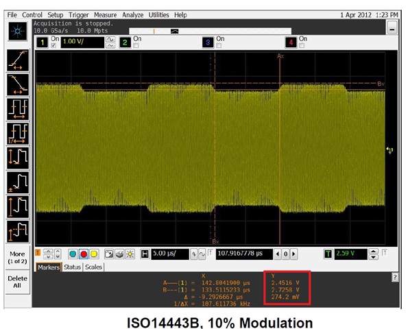
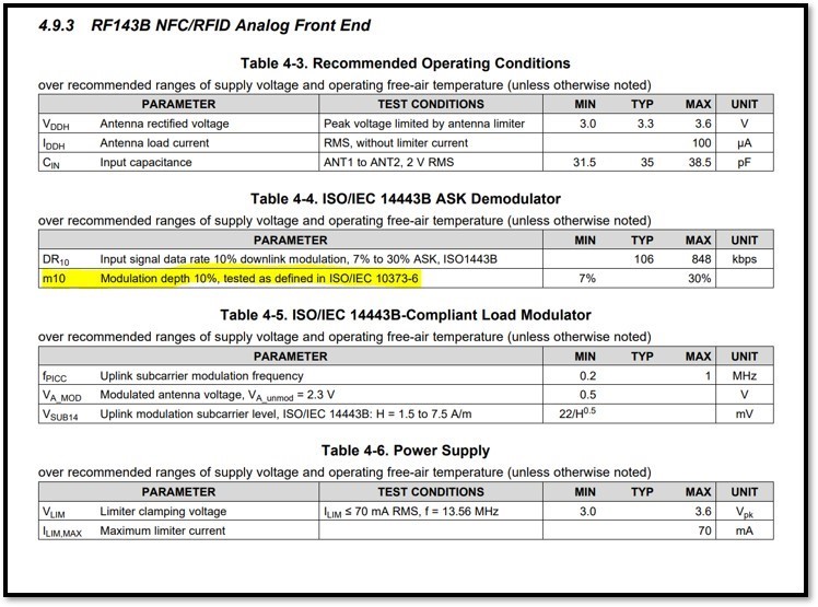
Could you help clarify the data sheet terminology? In section 4.9.3, it shows that the RF430 expects a 7-30% modulation depth for the analog inputs, shown in picture 2 below. Is this actual modulation depth, or modulation index?

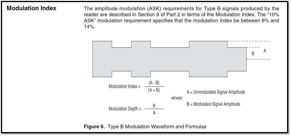
To my knowledge, modulation index and index is calculated according to the formulas in the first image below. Where I’m confused is that modulation depth is typically listed as a percentage of unmodulated voltage, but the data sheet seems to list it as the percentage decrease of the unmodified voltage. Can you help clarify if the data sheet is specifying in modulation depth, or is it actually in modulation index?

Thanks,

Luke

  • Hi Luke,

      I think modulation depth is used interchangeably with modulation index here. I believe on the datasheet, it refers to the formula (A - B) / (A + B) for test purpose.  

  • Hi Charles,

    Could you point out where in the data sheet that formula is referenced? All other documentation I've read either explicitly defines the differences and relationship between mod index and mod depth, or only speaks on mod index. 

    We’ve been evaluating PICC/PCD communication with the RF430. It seems like we begin to have some communication issues whenever we go higher than 93% modulation depth (~3.6% mod index). We can correct this issue by lowering modulation depth to ~91% (~4.5% modulation index). This is another reason why we were interested in specifically understanding this parameter on the data sheet.

    Best,

    Luke

  • Hi Luke,

     I think I will recall my earlier answer. While the RF430CL331H ds (which is a PICC) does not explain how modulation depth is define, I find the TRF7970A (a PCD) transceiver to have the below notes about the depth. 

    6.15.3.2.8 Modulator and SYS_CLK Control Register (0x09)

    The frequency of SYS_CLK (pin 27) is programmable by the bits B4 and B5 of this register. The frequency of the TRF7970A system clock oscillator is divided by 1, 2 or 4 resulting in available SYS_CLK frequencies of 13.56 MHz or 6.78 MHz or 3.39 MHz. The ASK modulation depth is controlled by bits B0, B1 and B2. The range of ASK modulation is 7% to 30% or 100% (OOK). The selection between ASK and OOK (100%) modulation can also be done using direct input OOK (pin 12). The direct control of OOK/ASK using OOK pin is only possible if the function is enabled by setting B6 = 1 (en_ook_p) in this register (0x09) and the ISO Control Register (0x01, B6 = 1). When configured this way, the MOD (pin 14) is used as input for the modulation signal. Table 6-36 describes the Modulator and SYS_CLK Control register

    In this TRF7970 Training material, there is a 10% ASK diagram. If you look at the delta on the voltage scale, it is 274.2mV and the unmodulated carrier is 2.7258V. Dividing 274.2mV by 2.7258V gives 10%. I would assume the RF430CL331H means the 10% modulation depth as in percentage. 

    Here is the training material.

    8688.TRF79xxA_Training_05_2013.pdf