This thread has been locked.

If you have a related question, please click the "Ask a related question" button in the top right corner. The newly created question will be automatically linked to this question.

CC1101 - frequency synthesizer calibration

Other Parts Discussed in Thread: CC1101

Hey everybody,

According to datasheet there are 3 way of handling the repetetive calibration of the CC1101's vco and the charge pump. One option is to skip the charge pump current calibration which reduces the total calibration time. When charge pump current calibration is disabled the calibration time should be reduced from 712/724 µs to 145/157 µs. But for some reason it remains the same in my case.

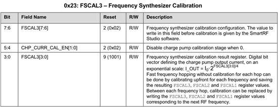
The procedure is to make a complete calibration and then to disable the charge pump current calibration by writing 0s to the bit 4 and 5 of the FSCAL register (see figure below). I did that and checked afterwards the register to be sure that these both bits are cleared and the other bits remains unchanged, which is the case.

But the total calibration time that I measure is still the same (~720µs instead of ~160µs) no matter if I do the charge pump current calibration or not. What could be a reason for that?

Thanks for any help.

with best regards, Frank

  • Hi,

    What is the MCSM0.FS_AUTOCAL set to? Do you have the piece of the code showing how you do the calibration?

  • Hi and thank you very much for your helpful input even though you actually were asking me even more questions. But it helped to improve my understanding of the CC1101 and cleared a misunderstanding. In fact I misinterpreted my own measurements a little bit. Nevertheless it still does not give me an answer to my main problem which is that I measure always at least approx. 700µs between the beginning of sending and the end of receiving a message no matter what setting I use.

    Btw. to answer your question, I set MCSM0.FS_AUTOCAL to 1 ...and 2 as well as 3 and 0.. knowing well that only 1 is recommended value. But ironically all settings led to the same result and to my misinterpretation. Hence I have to correct my self.. the reduction of calibration time does work.

    Furthermore, concerning the calibration, I only use the respective functions from the example code (mrfi_radio.c) provided by TI. Which is in the end nothing else than strobing SIDLE (forcing CC1101 to enter idle mode) followed by strobing SRX (forcing CC1101 to enter receive mode again). And presuming MCSM0.FS_AUTOCAL is set to 1 or 2 it causes a full calibration (according to the data sheet adding a ~ 720µs delay of wating for the CC1101).

    But for some reason there is always another delay I cannot explain and neither does the data sheet. E.g. I have a general signal delay/latency due to the modulation process and calibration of approx 1.4ms, but then no matter which setting (MCSM0.FS_AUTOCAL= 0 | 1 | 2 | 3) I'm going to use this delay will never be below 700 µs even when I set it to disable the charge pump calibration (see OP). In the first place I thought these 700µs were caused by the calibration routines but since I checked all possible calibration configurations I can definitely rule out this option.

    Maybe it's better to start a new thread since my question has now changed to:

    What causes these 700µs during normal operating mode (sending messages)?

    But perhaps you can already answer that question...

    many thanks, Frank

  • Hi Frank

    Can you post a sample code and register settings that ilustrates the issue you are seeing?

    Using default register settings from SmartRF Studio I got the following time delay on the CC1101:

    • From IDLE -> RX with calibration:     (MCSM0.FS_AUTOCAL= 1)  ~764 us
    • From IDLE -> RX with charge pump calibration disabled: (FSCAL3.CHP_CURR_CAL_EN=0) ~198 us
    • From IDLE -> Rx without calibration:          (MCSM0.FS_AUTOCAL= 0)  ~ 53 us
  • Add also a description of how you measure "700µs between the beginning of sending and the end of receiving a message ..."

    Do you use any of the internal CC1101 signals, that can be made available on the GDO pins, when you do the measurements (i.e to determine start of transmission and end of reception)? Signals to look are described in table 41 in the CC1101 data sheet.

  • Can you give us a feedback if you solved the issue ? and how ?

    I'm looking forward to use this chip and I am also concerned about calibration delays ...

    Thanks