This thread has been locked.

If you have a related question, please click the "Ask a related question" button in the top right corner. The newly created question will be automatically linked to this question.

CC1120 PQT and others questions

Other Parts Discussed in Thread: CC1120

My settings:
////////////////////////////////////////////////////////////////////////////////////////////////////////
halRfWriteReg(CC1120_SYNC2,0xBE);
halRfWriteReg(CC1120_SYNC1,0x9D);
halRfWriteReg(CC1120_SYNC0,0x31);

//halRfWriteReg(CC1120_MODCFG_DEV_E,0x02); // Fdiv = 4 kHz (default)
halRfWriteReg(CC1120_DCFILT_CFG,0x1C);

halRfWriteReg(CC1120_PREAMBLE_CFG1,0x28); // 8 bytes (0xAA)
halRfWriteReg(CC1120_PREAMBLE_CFG0,0x22); // Preamble detection enabled PQT // Start-up Timer=16 symbols // PQT = 2

halRfWriteReg(CC1120_SYNC_CFG1,0x24); // PQT Enable; (max 2 bit error???)
halRfWriteReg(CC1120_SYNC_CFG0,0x11); // 24 bits; < 2 bit error in last received sync byte

halRfWriteReg(CC1120_IQIC,0xC6);
halRfWriteReg(CC1120_CHAN_BW,0x14); // CH filter = 10 eAo
halRfWriteReg(CC1120_MDMCFG0,0x01); // Viterbi detection disabled

halRfWriteReg(CC1120_AGC_REF,0x20);
halRfWriteReg(CC1120_AGC_CS_THR,0x19);
halRfWriteReg(CC1120_AGC_CFG1,0xA9);
halRfWriteReg(CC1120_AGC_CFG0,0xCF);
halRfWriteReg(CC1120_FIFO_CFG,0x00);
halRfWriteReg(CC1120_SETTLING_CFG,0x0E);

halRfWriteReg(CC1120_FS_CFG,0x14); // 410.0 - 480.0 MHz band
halRfWriteReg(CC1120_PKT_CFG1,0x00); // CRC off + disable append mode
halRfWriteReg(CC1120_PKT_CFG0,0x00); // length = CC1120_PKT_LEN

halRfWriteReg(CC1120_PA_CFG2,0x69); // TX power 5 dB
halRfWriteReg(CC1120_PA_CFG0,0x56);
halRfWriteReg(CC1120_IF_MIX_CFG,0x00);

halRfWriteExtReg(CC1120_FREQOFF_CFG,0x22);
halRfWriteExtReg(CC1120_FREQ2,0x6C); // 434 MHz
halRfWriteExtReg(CC1120_FREQ1,0x80);

halRfWriteExtReg(CC1120_FS_DIG1,0x00);
halRfWriteExtReg(CC1120_FS_DIG0,0x5F);
halRfWriteExtReg(CC1120_FS_CAL1,0x40);
halRfWriteExtReg(CC1120_FS_CAL0,0x0E);
halRfWriteExtReg(CC1120_FS_DIVTWO,0x03);
halRfWriteExtReg(CC1120_FS_DSM0,0x33);
halRfWriteExtReg(CC1120_FS_DVC0,0x17);
halRfWriteExtReg(CC1120_FS_PFD,0x50);
halRfWriteExtReg(CC1120_FS_PRE,0x6E);
halRfWriteExtReg(CC1120_FS_REG_DIV_CML,0x14);
halRfWriteExtReg(CC1120_FS_SPARE,0xAC);
halRfWriteExtReg(CC1120_FS_VCO0,0xB4);
halRfWriteExtReg(CC1120_XOSC5,0x0E);
halRfWriteExtReg(CC1120_XOSC1,0x03);

halRfWriteReg(CC1120_PKT_LEN, 12); // Max payload data length
////////////////////////////////////////////////////////////////////////////////////////////////////////////////////////////////////////////

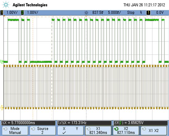
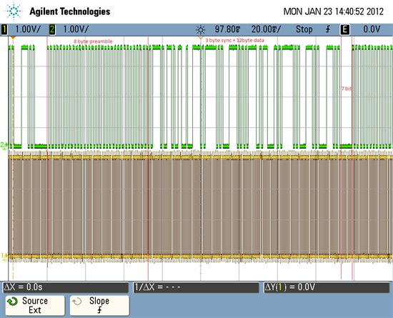
From generator we send the packet (25 dyte) :
0xAAAAAAAAAAAAAAAA - preamble (8 byte)
0xBE9D31 - our sync (3 byte)
0x1F5FD43EABE5C35FD43D41EA - coding data (12 byte)
0x0000 - 2 byte
CRC disabled - we calculate separately

Result: the received data (12 byte) - correct (0x1F5FD43EABE5C35FD43D41EA)
But, if we send incorrect preamble, for example: 0x8B8B8B8B8B8B8B8B, or even packet: BE9D31 1F5FD43EABE5C35FD43D41EA 0000000000000000 - (25 byte without preamble(0xAA))    -   received data (12 byte) - correct (0x1F5FD43EABE5C35FD43D41EA). Though Preamble detection enabled.

Questions:
1) We set - PQT enabled for SYNC and PREAMBLE. SYNC_CFG1.SYNC_THR [4:0] & PREAMBLE_CFG0.PQT [3:0] - set quantity Bit Error (???) and how calculate these values ? Because, if check PQT_SYNC_ERROR we see PQT_ERROR[7:4] = 1111b and SYNC_ERROR[3:0] = 00XXb.
2) SYNC_CFG0.SYNC_NUM_ERROR[1:0] = 0x01 - 2 bit error in all sync word or only in 1 byte SYNC0 ?
3) Earlier we working with ADF, but want use CC1120. Where exactly set admissible bit error for Sync word and Preamble?
4) It is possible on СС1120 to make so:
in TX side we use packet with 64 bits preamble, 24 bit sync and some data, but
on RX side - when received only 24 or 32 bits preamble (with Bit error < 2), we start search - sync word, and when sync word was detected - we get data.
I assume that it can be made so - TX device: config PREAMBLE_CFG1.NUM_PREAMBLE = 8 bytes , and
RX device: config PREAMBLE_CFG1.NUM_PREAMBLE = 3 or 4 bytes ?
5) You can give more information about MDMCFG0.VITERBI_EN ???

  • 0) If you don't gate on PQT (5.7 in the userguide) you will be able to receive valid data using a very short preamble or in some cases even without a preamble. In CC1120 the preamble is only used to settle the AGC, bit and byte sync are performed on the sync word.

    1) Note that your setting for SYNC_CFG1 is wrong if you want to gate on PQT.

    From the userguide:

    PQT Gating:
    When SYNC_CFG1.DEM_CFG = 010b or 110b, the demodulator will not start to look for a
    sync word before a preamble is detected. The preamble detector must be enabled for this
    feature to work (PREAMBLE_CFG0.PQT_EN = 1). See Section 5.7 for more details on PQT.

    SYNC_CFG1.SYNC_THR: The value used in SmartRF Studio should be used as a starting point. If you get a problem with false sync, adjust the threshold.

    2) Bit Check on Sync Word
    This feature is enabled through SYNC_CFG0.SUW_NUM_ERROR and allows for bit check on
    the last sync word byte. This feature is especially useful if the sync word used has weak
    correlation properties 

    3) Preamble: As stated below preamble is only used to settle the AGC and hence if not PQT gating is used CC1120 does not look for bit errors in the preamble.

         Sync: The sync detector in CC1120 is correlator based (5.6 in the userguide) and not bit pattern based. In other words: The sync word detector compares the incomming signal with a shape set by the sync word register. How much the incomming wave could be from the wave defined by the sync word is set by SYNC_CFG1.SYNC_THR (described on page 69 in the userguide)

    4) For RX the setting in the PREAMBLE_CFG1.NUM_PREAMBLE register does not have any meaning. If not PQT gating is used the CC1120 will start looking for a sync word from the first preamble bit.

    5) MDMCFG0.VITERBI_EN: Viterbi Detection Enable. Enabling Viterbi detection improves the sensitivity. The latency from the antenna to the signal is available in the RXFIFO or on the GPIO is increased by 5 bits for 2-ary modulation formats and 10 bits for 4-ary modulation formats. Minimum packet length = 2 bytes when Viterbi Detection and 4-(G)FSK is enabled.

    The default value given by SmartRF Studio should be used.

  • If I wanted gate on PQT? I used the default value given by SmartRF Studio 7 ver.1.6.1.

    My settings ver.2.0. (change only SYNC_CFG1)  :
    halRfWriteReg(CC1120_PREAMBLE_CFG1,0x28); // 8 bytes (0xAA)
    halRfWriteReg(CC1120_PREAMBLE_CFG0,0x2A); // Preamble detection enabled PQT // Start-up Timer=16 symbols //
    halRfWriteReg(CC1120_SYNC_CFG1,0x2A); // Preamble Qualifier enabled; - (default)
    halRfWriteReg(CC1120_SYNC_CFG0,0x11); // 24 bits; < 2 bit error in last received sync byte

    0) "In CC1120 the preamble is only used to settle the AGC" - first fol all I need detected our preamble, because PREAMBLE_CFG0.PQT_EN = 1 and SYNC_CFG1.DEM_CFG = 010b. Only when preamble - found, begins settles AGC. I have correctly understood ?


       When  PQT - enabled  .  Preamble  used for syncronization with sync word too?
       I dont have a problem with false sync, if I receive correct data.


    3) When PQT gating - ON, we look for bit errors in the preamble. I will result 3 examples as I understand:
    A) In TX we sent incorrect preamble, example : 0xFFFFFFFFFFFFFFFF (8 byte) + sync(correct) (3byte) + data (12 byte)
    In RX we search preamble (0xAA). --> PQT_SYNC_ERR.PQT_ERROR should be 32(dec). Correct?

    from datasheet: The preamble quality estimator uses an 8 bits wide correlation filter to find a valid preamble. A
    preamble qualifier value is available through the PQT_SYNC_ERR.PQT_ERROR register field while the
    threshold is configured with the register field PREAMBLE_CFG0.PQT.
    from datasheet: PQT_ERROR is only 4 bits wide PQT_ERROR = MIN[actual PQT qualifier value] modulo 16
    PQT_ERROR = 1111b ????
    from datasheet: A preamble is detected when the calculated preamble qualifier value (PQT_SYNC_ERR.PQT_ERROR) is less than PQT).

    In my example PQT_SYNC_ERR.PQT_ERROR (1111b) > PQT (1010b) --> A preamble is not detected ---> When SYNC_CFG1.DEM_CFG = 010b, the demodulator will not start to look for a sync word before a preamble is detected ----> we can not RX our data.

    B) In TX we sent incorrect preamble, example : 0xBBBBBBBBAAAAAAAA (8 byte) + sync(correct) (3byte) + data (12 byte)
    In RX we search preamble (0xAA). --> PQT_SYNC_ERR.PQT_ERROR should be 8(dec). Correct?

    PQT_ERROR = 0100b ????
    from datasheet: A preamble is detected when the calculated preamble qualifier value (PQT_SYNC_ERR.PQT_ERROR) is less than PQT).

    In my example PQT_SYNC_ERR.PQT_ERROR (0100b) < PQT (1010b) --> A preamble is detected --->start to look a sync word (our sync word - correct 100%)----> we RX our data.

    C) In TX we sent incorrect preamble, example : 0xCCCCCCCCCCCCCCCC (8 byte) + sync(correct) (3byte) + data (12 byte)
    In RX we search preamble (0xAA). --> PQT_SYNC_ERR.PQT_ERROR should be 16(dec). Correct?

    PQT_ERROR = 0000b ????
    from datasheet: A preamble is detected when the calculated preamble qualifier value (PQT_SYNC_ERR.PQT_ERROR) is less than PQT).

    In my example PQT_SYNC_ERR.PQT_ERROR (0000b) < PQT (1010b) --> A preamble is detected? --->start to look a sync word (our sync word - correct 100%)----> we RX our data.

  • Before I go into your examples in details, note that you use the wrong setting for SYNC_CFG1if you want to gate on PQT. Note that the correct setting is: SYNC_CFG1=0x4A.

  • on 69 page datasheet:  if we set 0x4A, then SYNC_CFG1.DEM_CFG    = 100b   -   PQT gating disabled.  ---> demodulator won't wait when preamble is detected and will start to look for a sync word... or not ?

  • No.

    Remember  that SYNC_CFG1.DEM_CFG is the 3 most significat bits, hence 010b PQT gating enabled correspond to 0x4B. 100b will correspond to 0x8B...

  • thx, for answer, I haven't paid attention on  Bit.no this register.

  • //////////////////////////////////////////////////////////////////
    halRfWriteReg(CC1120_IOCFG0, 0x06); //Set GPIO0 to be packet received signal
    halRfWriteReg(CC1120_IOCFG2, 0x0B); // see setting PQT_REACHED

    halRfWriteReg(CC1120_SYNC2,0xBE);
    halRfWriteReg(CC1120_SYNC1,0x9D);
    halRfWriteReg(CC1120_SYNC0,0x31);


    halRfWriteReg(CC1120_SYNC_CFG1,0x4A); // PQT Enable;
    halRfWriteReg(CC1120_SYNC_CFG0,0x11); // 24 bits; 1 bit error in last received sync byte
    //halRfWriteReg(CC1120_MODCFG_DEV_E,0x02); // Fdiv = 4 kHz (default)
    halRfWriteReg(CC1120_DCFILT_CFG,0x1C); // from RF Smart_Studio
    halRfWriteReg(CC1120_PREAMBLE_CFG1,0x18); // 4 bytes (0xAA)
    halRfWriteReg(CC1120_PREAMBLE_CFG0,0x2A); // Preamble detection enabled PQT // Start-up Timer=16 symbols // PQT = 10

    halRfWriteReg(CC1120_IQIC,0xC6); // from RF Smart_Studio
    halRfWriteReg(CC1120_CHAN_BW,0x14); // CH filter = 10 kHz
    halRfWriteReg(CC1120_MDMCFG0,0x05); // Viterbi detection Enabled
    // halRfWriteReg(CC1120_DRATE2, 0x40); // 1,2 kbps defualt
    // halRfWriteReg(CC1120_DRATE1, 0x62);
    // halRfWriteReg(CC1120_DRATE2, 0x4E);
    halRfWriteReg(CC1120_AGC_REF,0x20); // from RF Smart_Studio
    halRfWriteReg(CC1120_AGC_CS_THR,0x19); // from RF Smart_Studio

    halRfWriteReg(CC1120_AGC_CFG1,0xA9); // from RF Smart_Studio
    halRfWriteReg(CC1120_AGC_CFG0,0xCF); // from RF Smart_Studio

    halRfWriteReg(CC1120_FIFO_CFG,0x00);
    halRfWriteReg(CC1120_SETTLING_CFG,0x0E); // from RF Smart_Studio
    halRfWriteReg(CC1120_FS_CFG,0x14); // 410.0 - 480.0 MHz band
    halRfWriteReg(CC1120_PKT_CFG1,0x00); // CRC off + disable append mode
    halRfWriteReg(CC1120_PKT_CFG0,0x00); // Fixed packet length mode ( length = CC1120_PKT_LEN)

    halRfWriteReg(CC1120_PA_CFG2,0x7F); // TX power max dB
    halRfWriteReg(CC1120_PA_CFG0,0x56); // from RF Smart_Studio
    halRfWriteReg(CC1120_PKT_LEN, 12); // Max payload data length

    halRfWriteReg(CC1120_IF_MIX_CFG,0x00); // from RF Smart_Studio
    halRfWriteExtReg(CC1120_FREQOFF_CFG,0x22); // from RF Smart_Studio
    halRfWriteExtReg(CC1120_FREQ2,0x6C); // 434 MHz
    halRfWriteExtReg(CC1120_FREQ1,0x80);

    /***************** from RF Smart_Studio ********************/
    halRfWriteExtReg(CC1120_FS_DIG1,0x00);
    halRfWriteExtReg(CC1120_FS_DIG0,0x5F);
    halRfWriteExtReg(CC1120_FS_CAL1,0x40);
    halRfWriteExtReg(CC1120_FS_CAL0,0x0E);
    halRfWriteExtReg(CC1120_FS_DIVTWO,0x03);
    halRfWriteExtReg(CC1120_FS_DSM0,0x33);
    halRfWriteExtReg(CC1120_FS_DVC0,0x17);
    halRfWriteExtReg(CC1120_FS_PFD,0x50);
    halRfWriteExtReg(CC1120_FS_PRE,0x6E);
    halRfWriteExtReg(CC1120_FS_REG_DIV_CML,0x14);
    halRfWriteExtReg(CC1120_FS_SPARE,0xAC);
    halRfWriteExtReg(CC1120_FS_VCO0,0xB4);
    halRfWriteExtReg(CC1120_XOSC5,0x0E);
    halRfWriteExtReg(CC1120_XOSC1,0x03);
    /**********************************************************/

    When I TX 100 packets with max TX_power (very good signal + TX and RX device connected by a wire --> Perfect conditions). Whether should accept all packages always in such conditions? How value PQT_ERROR is calculated, if used 8 bit correlator, but PQT_ERROR can be more than 8 ?
    When PREAMBLE_CFG0=0x2F ---> PQT_REACHED always high.
    PREAMBLE_CFG0=0x2A ---> RX packets = 100.
    PREAMBLE_CFG0=0x28 ---> RX packets = 100.
    PREAMBLE_CFG0=0x27 ---> RX packets = 100.
    PREAMBLE_CFG0=0x26 ---> RX packets = 66, error packets = 31.
    PREAMBLE_CFG0=0x24 ---> RX packets = 11.
    PREAMBLE_CFG0=0x20 ---> RX packets = 3 - 0.

    On a task condition is required: detected preamble whis errors <= 2, if 3 errors ---> this is noise. Can i do this on CC1120?

  • Could you explain a why you want to gate on preamble and why it is important to gate on 3 errors? Could you use gating on carrier sense?

  • Such requirements of the customer. Earlier, (1st release) we used ADF, and probabilities of reception of a package was calculated (Another man) for ADF.
    Nevertheless, I ask you to explain How value PQT_ERROR is calculated. 

    ++++++++++++++++++++++++++++++++++
    In cycle i sent packets (fragments from code):

    while (TRUE)
    // Send 100 packets
    for (i = 0; i < 100; i++)
    txSendPacket(transmit_packet, 12);


    static uint8 txSendPacket(uint8* data, uint8 length)
    {
    uint16 key;
    packetSent = FALSE;

    HAL_SPI_BEGIN; // SPI Enable
    // Write data to FIFO
    halRfWriteFifo(data, length);

    // Set radio in transmit mode
    halRfStrobe(CC1120_STX);

    // Wait for packet to be sent
    key = halIntLock();
    while(!packetSent)
    {
    halMcuSetLowPowerMode(HAL_MCU_LPM_3);
    key = halIntLock();

    }
    halIntUnlock(key);

    return(0);
    }
    ++++++++++++++++++++++++++++++++++++++++++++
    On Oscilloscope i see delay = 5.77 ms between each packets. This is RSSI Update Rate <= 5.77 ms ???

     On 1st picture i change preamble = 4 byte only. Data rate 1.2 kbps. With data rate =2.4  kbps -->  delay = 2.88 ms.


  • - The CC1120 uses a correlator to detect preamble hence the chip compares to waveforms. The PQT_ERROR is a measure on how equal these waveforms are and has basically nothing to do with the number of bit errors.With CC1120 the descition if you have received a valid package is normally taken with sync detect: If the radio detects a valid sync word it receives the rest of the data, if not it returns to sleep. It is important to fully understand your customers requirement.

    - It is not possible to know why you have the timing you have on package sending without knowing your full setup. In the RFEND_CFG0 register you can set which state you go to when you finish sending a package. if TXOFF_MODE is set to TX the radio can send packages back to back, if the radio is setup to return to IDLE after each package the timing will be different.

  • With what SNR you get sensitive= -123dBm?

  • Around 5dB SNR

  • We use XOSC = 32 Mhz.  

    I wanted to look on pin GPIO2  freq  internal RCOSC= 32 kHz. (IOCFG2.GPIO2_CFG = CLOCK_32K ). WOR_CFG0=0x00. But on pin №=4 we see freq = 16 kHz.   why?

  • To get correct frequency the rc-oscillator has to be calibrated. This is done in IDLE.

    Try the following:

    SRES

    IOCFG2=0x36

    WOR_CFG0=0x24

    IDLE

  • When we set the data rate > 4.8 Kbps, the data begin RX incorrect.
    Modulation format: 2-FSK
    For example, 8 kbps with frequency Deviation = 8 kHz.
    RX filter = 25 kHz


    I Change only this registers:
    halRfWriteReg(CC1120_MODCFG_DEV_E, 0x04); // Fdev = 8 kHz
    halRfWriteReg(CC1120_DCFILT_CFG, 0x1C); // from SmartRF_Studio
    halRfWriteReg(CC1120_IQIC, 0xC6); // from SmartRF_Studio

    halRfWriteReg(CC1120_CHAN_BW, 0x08); // RX filter = 25 kHz

    halRfWriteReg(CC1120_DRATE2, 0x70); // data rate = 8 kbps
    halRfWriteReg(CC1120_DRATE1, 0x62);
    halRfWriteReg(CC1120_DRATE0, 0x4E);

    It should be working, but I don`t understand why is not working.

  • Without the full register settings you are using it is a bit difficult to test in the lab but from the numbers you give I suspect that the RX bandwidth is to small. With 8kHz deviation and 8kbps the theoretical minimum RX bandwidth is 24kHz. If you have a small frequency offset in the system part of your signal will be filtered and the RX sensitivity will be a lot poorer. Increase the RX bandwidth to see if this helps.

  • I increase the RX BW = 33 kHz, 28 kHz and this is not help---> all packets incorrect. ( RX BW > 2 * data rate )

    This low data rate i see packets on oscilliscope (the similar form), When I set data rate, example 32 kbps, 64 kbps or above ----> i see ~ "noise+ some bits" 

    My full reg settings :

    halRfWriteReg(CC1120_IOCFG0, 0x06);
    halRfWriteReg(CC1120_IOCFG3, 0x14);  // MCU wakeup
    halRfWriteReg(CC1120_IOCFG2, 0x36);  // 

    halRfWriteReg(CC1120_SYNC2, 0xBE);
    halRfWriteReg(CC1120_SYNC1, 0x9D);
    halRfWriteReg(CC1120_SYNC0, 0x31);

    halRfWriteReg(CC1120_SYNC_CFG1, 0x4A);     // PQT Enable; 
    halRfWriteReg(CC1120_SYNC_CFG0, 0x11);     // 24 bits; 1 bit error in last received sync byte  
     

    halRfWriteReg(CC1120_MODCFG_DEV_E,0x04); // Fdev = 8 kHz
    halRfWriteReg(CC1120_DCFILT_CFG, 0x1C);

    halRfWriteReg(CC1120_PREAMBLE_CFG1,0x18); // 8 bytes (0xAA) 0x28 1 byte 0xAA
    halRfWriteReg(CC1120_PREAMBLE_CFG0,0x2A); // Preamble detection enabled PQT // Start-up Timer=16 symbols // PQT = 10
    halRfWriteReg(CC1120_IQIC, 0xC6);

     halRfWriteReg(CC1120_CHAN_BW, 0x06); // RX BW filter =  33.333333 kHz
    halRfWriteReg(CC1120_MDMCFG0, 0x05); // Viterbi detection Enabled

    halRfWriteReg(CC1120_DRATE2, 0x70); // 8 kbps
    halRfWriteReg(CC1120_DRATE1, 0x62);
    halRfWriteReg(CC1120_DRATE0, 0x4E);

    halRfWriteReg(CC1120_AGC_REF, 0x20);
    halRfWriteReg(CC1120_AGC_CS_THR, 0x0C); // CS_THR -90 dBm
    halRfWriteReg(CC1120_AGC_CFG1, 0xA9);
    halRfWriteReg(CC1120_AGC_CFG0, 0xCF);

    halRfWriteReg(CC1120_FIFO_CFG, 0x00);
    halRfWriteReg(CC1120_SETTLING_CFG, 0x0E);
    halRfWriteReg(CC1120_FS_CFG, 0x14); // 410.0 - 480.0 MHz band

    halRfWriteReg(CC1120_PKT_CFG1, 0x00); // CRC off + disable append mode
    halRfWriteReg(CC1120_PKT_CFG0, 0x00); // Fixed packet length mode ( length = CC1120_PKT_LEN)

    halRfWriteReg(CC1120_PA_CFG2, 0x74); // TX power 10 dB
    halRfWriteReg(CC1120_PA_CFG0, 0x6E);
    halRfWriteReg(CC1120_PKT_LEN, 12); // Max payload data length
    /********* settings from SmartRF_Studio *************/
    halRfWriteExtReg(CC1120_IF_MIX_CFG, 0x00);
    halRfWriteExtReg(CC1120_FREQOFF_CFG,0x22);
    halRfWriteExtReg(CC1120_FREQ2, 0x6C); // 434 MHz
    halRfWriteExtReg(CC1120_FREQ1, 0x80);
    //halRfWriteExtReg(CC1120_FREQ0, 0x21);
    halRfWriteExtReg(CC1120_FS_DIG1, 0x00);
    halRfWriteExtReg(CC1120_FS_DIG0, 0x5F);
    halRfWriteExtReg(CC1120_FS_CAL1, 0x40);
    halRfWriteExtReg(CC1120_FS_CAL0, 0x0E);
    halRfWriteExtReg(CC1120_FS_DIVTWO, 0x03);
    halRfWriteExtReg(CC1120_FS_DSM0, 0x33);
    halRfWriteExtReg(CC1120_FS_DVC0, 0x17);
    halRfWriteExtReg(CC1120_FS_PFD, 0x50);
    halRfWriteExtReg(CC1120_FS_PRE, 0x6E);
    halRfWriteExtReg(CC1120_FS_REG_DIV_CML,0x14);
    halRfWriteExtReg(CC1120_FS_SPARE, 0xAC);
    halRfWriteExtReg(CC1120_FS_VCO0, 0xB4);
    halRfWriteExtReg(CC1120_XOSC5, 0x0E);
    //halRfWriteExtReg(CC1120_XOSC2, 0x05);
    halRfWriteExtReg(CC1120_XOSC1, 0x03); 

  • For quick tests in the lab I always use SmartRF Studio. I have not typed in all your settings, just set the deviation to 8kHz and the datarate to 8kbps. I also set the AGC_CS_THE=0x0C and SYNC_CFG1=0x4A and I have no problem receiving.

  • I found my error in settings: halRfWriteReg(CC1120_PA_CFG0, 0x6E);  I set this register correctly and all is working.

    Thanks you for answers.

  • In  SmartRF Studio max data rate = 100 kbps.

    1) Can i test bit rata>100 kbps with 2-FSK modulation or only use 4-FSK? 

    2) length preamle depend on data rate? (with 4 byte preamble and 64kbps --> don`t working, with 8 byte preamble --> it`s ok)   

    3) Can i get bit rate > 200 kbps on CC1120 ? 


  • 1,3) The CC1120 datarate is limited to 2*RX_BW hence limiting the symbolrate to 100ksps.

    2) With not working, do you mean that you don't manage to get data over the link? Could you provide me with a SmartRF Studio config files with the settings you are using so I can look more closely into it?

  • 2) With this settings RX only ~50% packets (50 from 100)- SmartRF Studio config:
    # Carrier frequency = 434.000000
    # Symbol rate = 64
    # Bit rate = 64
    # Deviation = 31.982422
    # Manchester enable = false
    # Bit rate = 64
    # Modulation format = 2-FSK
    # Bit rate = 64
    # RX filter BW = 200.000000
    # TX power = 11.5*
    # PA ramping = true
    # Packet length mode = Fixed
    # Whitening = false
    # Address config = No address check.
    # Packet length = 12
    # Device address = 0
    halRfWriteReg(IOCFG3,0x14);
    halRfWriteReg(IOCFG2,0x36);
    halRfWriteReg(IOCFG0,0x06);
    halRfWriteReg(SYNC2,0xBE);
    halRfWriteReg(SYNC1,0x9D);
    halRfWriteReg(SYNC0,0x31);
    halRfWriteReg(SYNC_CFG1,0x4A);
    halRfWriteReg(SYNC_CFG0,0x11);
    halRfWriteReg(MODCFG_DEV_E,0x06);
    halRfWriteReg(DCFILT_CFG,0x15);
    halRfWriteReg(PREAMBLE_CFG1,0x18);
    halRfWriteReg(IQIC,0x00);
    halRfWriteReg(CHAN_BW,0x01);
    halRfWriteReg(MDMCFG0,0x05);
    halRfWriteReg(DRATE2,0xA0);
    halRfWriteReg(DRATE1,0x62);
    halRfWriteReg(DRATE0,0x4E);
    halRfWriteReg(AGC_REF,0x20);
    halRfWriteReg(AGC_CS_THR,0x19);
    halRfWriteReg(AGC_CFG1,0xA9);
    halRfWriteReg(AGC_CFG0,0xCF);
    halRfWriteReg(FIFO_CFG,0x00);
    halRfWriteReg(SETTLING_CFG,0x0E);
    halRfWriteReg(FS_CFG,0x14);
    halRfWriteReg(PKT_CFG1,0x00);
    halRfWriteReg(PKT_CFG0,0x00);
    halRfWriteReg(PA_CFG2,0x7A);
    halRfWriteReg(PA_CFG0,0x7A);
    halRfWriteReg(PKT_LEN,0x0С);
    halRfWriteReg(IF_MIX_CFG,0x00);
    halRfWriteReg(FREQOFF_CFG,0x22);
    halRfWriteReg(FREQ2,0x6C);
    halRfWriteReg(FREQ1,0x80);
    halRfWriteReg(FS_DIG1,0x00);
    halRfWriteReg(FS_DIG0,0x5F);
    halRfWriteReg(FS_CAL1,0x40);
    halRfWriteReg(FS_CAL0,0x0E);
    halRfWriteReg(FS_DIVTWO,0x03);
    halRfWriteReg(FS_DSM0,0x33);
    halRfWriteReg(FS_DVC0,0x17);
    halRfWriteReg(FS_PFD,0x50);
    halRfWriteReg(FS_PRE,0x6E);
    halRfWriteReg(FS_REG_DIV_CML,0x14);
    halRfWriteReg(FS_SPARE,0xAC);
    halRfWriteReg(FS_VCO0,0xB4);
    halRfWriteReg(XOSC5,0x0E);
    halRfWriteReg(XOSC1,0x03);
    /////////////////////////////////////////////////

    I have another question:
    In RX Sniff mod, bi rate =1.2 kbps, preamble length=30 byte and signal detection CS_THR = -90 dBm. In SmartRF studio average recieve current when no packet recived = 0.147 mA. But I give minimum 0.410 mA. (On oscilloscope i see Tsleep= 195,903 ms , Trx+Twakeup = 1.7252 ms.


    with settings (values for WOR registers i use from SmartRF)
    halRfWriteReg(IOCFG3,0x14);
    halRfWriteReg(IOCFG2,0x36);
    halRfWriteReg(IOCFG0,0x06);
    halRfWriteReg(SYNC2,0xBE);
    halRfWriteReg(SYNC1,0x9D);
    halRfWriteReg(SYNC0,0x31);
    halRfWriteReg(SYNC_CFG1,0x4A);
    halRfWriteReg(SYNC_CFG0,0x11);

    halRfWriteReg(DCFILT_CFG,0x1C);
    halRfWriteReg(PREAMBLE_CFG1,0x28);
    halRfWriteReg(IQIC,0x00);
    halRfWriteReg(CHAN_BW,0x08);
    halRfWriteReg(MDMCFG0,0x05);
    halRfWriteReg(AGC_REF,0x20);
    halRfWriteReg(AGC_CS_THR,0x19);
    halRfWriteReg(AGC_CFG1,0xA0);
    halRfWriteReg(AGC_CFG0,0xCF);
    halRfWriteReg(FIFO_CFG,0x00);
    halRfWriteReg(SETTLING_CFG,0x03);

    halRfWriteReg(FS_CFG,0x14);
    halRfWriteReg(PKT_CFG1,0x00);
    halRfWriteReg(PKT_CFG0,0x00);
    halRfWriteReg(PA_CFG2,0x7A);
    halRfWriteReg(RFEND_CFG0,0x09);
    halRfWriteReg(PKT_LEN, 0x0C);

    halRfWriteReg(IF_MIX_CFG,0x00);
    halRfWriteReg(FREQOFF_CFG,0x22);
    halRfWriteReg(FREQ2,0x6C);
    halRfWriteReg(FREQ1,0x80);
    halRfWriteReg(FS_DIG1,0x00);
    halRfWriteReg(FS_DIG0,0x5F);
    halRfWriteReg(FS_CAL1,0x40);
    halRfWriteReg(FS_CAL0,0x0E);
    halRfWriteReg(FS_DIVTWO,0x03);
    halRfWriteReg(FS_DSM0,0x33);
    halRfWriteReg(FS_DVC0,0x17);
    halRfWriteReg(FS_PFD,0x50);
    halRfWriteReg(FS_PRE,0x6E);
    halRfWriteReg(FS_REG_DIV_CML,0x14);
    halRfWriteReg(FS_SPARE,0xAC);
    halRfWriteReg(FS_VCO0,0xB4);
    halRfWriteReg(XOSC5,0x0E);
    halRfWriteReg(XOSC2,0x05);
    halRfWriteReg(XOSC1,0x03);


    // calibrated RCOSC in IDLE_mod
    halRfWriteReg(WOR_CFG1,0x0C);
    halRfWriteReg(WOR_CFG0,0x24);
    halRfWriteReg(WOR_EVENT0_MSB,0x18);
    halRfWriteReg(WOR_EVENT0_LSB,0xD9);

  • 1) It looks like you have used the 1.2kbps settings as a starting point. This is a setting for narrow band and will not work well for higher datarates. For datarate 64kbps and 32kHz deviation a 0 IF setting has to be used. Try to start with the 200kbps setting and adjust the modulation format and the datarate/ deviation.

    2) How do you measure the current consumption? For this case you need to use a scope that measure the voltage over a series resistor and integrate the area under the curve to find the current consumption. A multimeter does some averaging and have some delay so they will not give you the correct result in this case. 

  • We use digital multimeter. 

    I found reason: when i set Sniff mod in SmartRF Studio , register XOSC2 set  0x05. When change this register (default value) --> all OK. 


  • We need TX/RX packet with Length =300. I see datasheet  7.1.5 (44 page). 

    halRfWriteReg(CC1120_PKT_CFG0, 0x40);

    halRfWriteReg(CC1120_PKT_LEN, 44);          // mod(300, 256) = 44

    halRfWriteFifo(transmit_packet, 128);

    halRfStrobe(CC1120_STX);

    //wait while a packet has been transmitted 

      halRfWriteReg(CC1120_PKT_CFG0, 0x00);               // Set PKT_CFG0.LENGTH_CONFIG = 0

    halRfWriteFifo(transmit_packet, 128);

    halRfStrobe(CC1120_STX);

    halRfWriteFifo(transmit_packet, 44);

    halRfStrobe(CC1120_STX);

    And I TX only 128 byte. 

    On 49 page: Additionally, for packets longer than 128 bytes, the  TX FIFO needs to be refilled while in TX. This means that the MCU needs to know the number of bytes that can be written to the RX FIFO and TX FIFO . ---->  i can set register RFEND_CFG0 - RFEND.TXOFF_MODE=10b. And when 128 bytes TX, we write to FIFO next 128 bytes -->TX, and 44 last bytes.


  • See appnote DN500 (http://www.ti.com/lit/an/swra109c/swra109c.pdf) for more information on how to send/ receive packages larger than the FIFO size.