This thread has been locked.

If you have a related question, please click the "Ask a related question" button in the top right corner. The newly created question will be automatically linked to this question.

Smart RF 04EB is not recognized in device manager

Other Parts Discussed in Thread: CC1150, CC1100, CC-DEBUGGER, CC2510

Hi, at the moment my SmartRF04EB is not recognized when i connect it with the pc. Yesterday it works. I read the DN300. But I' am not able to revive the board. The EM board works.

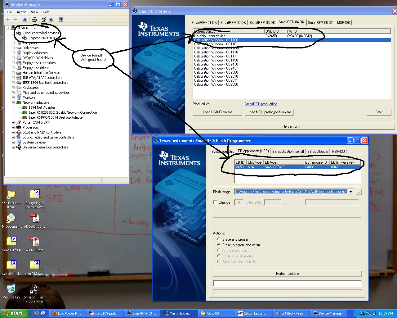
The EB is not shown in the progranner. Could anyone help me please.

  • A few suggestions:

    1) Remove all EM module from the 04EB and power up the board. Use either battery, DC or USB as power source. In all cases, the LEDs on the board will be tunred on, and the LCD will display "Chipcon SRF04EB Bo EM detected!". If this is the case, the firmware on the board is OK and the board should be listed in the device manager under "Cebal controlled devices".

    2) If nothing is displayed in the LCD or the board appears to be dead, you can try to enter the "Boot recovery mode". Turn power off. Then press and hold S1 AND the joystick (press it like a button) while turning power on the board. Nothing will be displayed on the LCD, but you should see the board in the device manager. You can now update the firmware on the board. The easiest way is to use a new version of SmartRF Studio. In the startup window, under the SmartRF04DK tab, the board should be listed as "No chip - new device". Double click that item on the list. Studio will now automatically program the latest firmware on the board. Reset the board and see what happens. Note that you do not need to be in the boot recovery mode to update the firmware. You can use the same firmware update mechanism in case 1.

    3) Make sure you select the "EB application (USB)" tab in the Flash Programmer. The board will not be listed in the "System on Chip" tab unless the 04EB is connected to one of the LPRF SoCs.

    4) If nothing of the above helps, try to uninstall all drivers for SmartRF04EB boards. In the device manager, select "View -> Show hidden devices". Delete (uninstall) all entires under "Cebal controlled devices". You can also consider to remove unkown devices under "Other devices". NB! Do this at your own risk. Set a restore point before uninstalling (To access the System Restore Wizard, click Start, and then click Help and Support. Click Performance and Maintenance, click Using System Restore to undo changes, and then click Run the System Restore Wizard). Reconnect your SmartRF04EB board to the PC and let the USB installation wizard run. Select "Automatic installation" when prompted by the wizard.

    I hope some of this might help.

  • Thanks for your suggestions Mozart. But not any fixed the problem. There is nothing on the display.

    I tried to connect the board to a another pc. But  this pc told me that the device is unknown, like my pc. My second Smart RF04EB board is known when i connect it with the pc.

    Do you have any other suggestions?

  • Have you found DN-300 SmartRF04 trouble shooting? http://focus.ti.com/general/docs/litabsmultiplefilelist.tsp?literatureNumber=swra105b

    Have you tried to re-load the boot loader using a JTAG module through the 10 pin header on the RF04 board, not the USB on the board? After the boot loader you can then download the SmartRF04 software via the USB port using Ti Flash programmer.


  • Hi H Steward,

    i am familiar with the DN300. But we have no EC2 Serial Adapter from Silicon Labs. So i am not able to reflash the bootloader. Because of this i can't space out that the bootloader is the problem. We have warranty for the kit, i hope that we can solve the problem without buying the EC2 Serial Adapter from Silicon Labs. In the meantime i contact our distributor.

    We are using the Smart RF 04 EB only for flashing or debuging the EMs.

  • Hello

    The "bootloader" is no more than the code to establish the USB interface and end points. Without this code the board will not be recognized.

    The SiLabs USB Debug Adapter is available from mouser.com (mouser number 634-DEBUGADPTR1-USB ) for $35. You can get the C8051F320 eval board for $99; it comes with the USB debug adapter to re-flash the SmartRF04. This board can also easily be used in place of the SmartRF04 to interface with Ti Flash Programmer and RF studio.  I can send you the details.

    HS


  • The TI SmartRF Flash Programmer application does not actually support the USB edition of SiLabs' debug adapter, it only supports the serial port EC2 adapter, and as far as I know, the serial adapters have almost been phased out and can be a bit hard to get a hold of these days. But I would guess that SiLabs might provide some flash programmer utility that can be used with the USB adapter instead (I haven't checked this myself).

    Did you try to use the SmartRF04EB's bootloader recovery mode? In case you program the SiLabs with a destructive application firmware (e.g. that disables USB interrupts so USB communication for the bootloader no longer works), you can make it boot without the bootloader trying to load the application firmware. This is done by pushing both the joystick and the S1 button when you turn it on.

    Unfortunately, after booting in this mode the EB will still look dead though (nothing on the LCD ("e.g. no "No EM detected"), nor the LEDs -- you might want to try it on your working EB first without mounting an EM, to you know you're doing it right), but if your bootloader is intact it should report itself on the USB bus, and you should be able to reprogram the application firmware via SmartRF Flash Programmer. If the bootloader is truly wiped the only option is an external programming adapter of some sort.

  • True, the TI SmartRF Flash Programmer application does not support the USB edition of SiLabs' debug adapter.

    You use the Silabs IDE to flash the Ti srf04eb_bootloader.hex into the RF04. The SiLabs IDE is a  free download and since you are flashing a SiLabs part there is no issue using it.  Since the SmartRF04 uses the Silabs C8051F320 it works perfectly. The connector is pin for pin compatible since it is only an upgrade from the old Silabs E2C serial module original supplied by Ti.

    For those with newer PC's that do not have a COM port it is a good low cost work around.


    Edit: typos

  • esy said:

    ...

    Did you try to use the SmartRF04EB's bootloader recovery mode? In case you program the SiLabs with a destructive application firmware (e.g. that disables USB interrupts so USB communication for the bootloader no longer works), you can make it boot without the bootloader trying to load the application firmware. This is done by pushing both the joystick and the S1 button when you turn it on. ..

    Hi esy,

    I tried the recovery mode without success. Windows is not able toe recognize the board. there is only the message that the device is not recognized. So i think  the bootloader is wiped.

  • I am having the exact same issue...Are there any work arounds to not having the E2C adapter....out of the box one of the boards is not recognized by multiple computers, the other board works great. however doing testing with only one board is not very possible.(900 bux down the drain)

  • Have you found DN-300 SmartRF04 trouble shooting? http://focus.ti.com/general/docs/litabsmultiplefilelist.tsp?literatureNumber=swra105b 

    Have you tired the reset as decribed by Esy in the post above yours?

  • Yea ive gone through the Dn-300 trouble shooting,  I have it narrowed down to a bootloader being back as described in section 6 of that document...I have been searching for a way to fix this without the ec2 seeing as how finding one available to purchase is almost impossible.

    The reset didn't work either. 

    The device is able to perform the PER test however that is the only thing it seems to be able to do.

    i have talked with several other groups of students working with the same boards...none have run into my specific issue yet, theirs seem to be not paying attention to how much power they supply when connecting it directly to the board and going over 3.3V and the board needs to sit and discharge for a day or so and then seems to come back to life.

    I have found a counterpart to the ec2 that uses usb instead made by SI Labs http://mouser.com/ProductDetail/Silicon-Laboratories/DEBUGADPTR1-USB/?qs=BJlw7L4Cy7%2fmpVaUa5fvbw%3d%3d


    this i have seen on some forums being described as being able to accompolish the task of redoing the bootloader...I hope this works this part is going to be at my house tomorrow morning.  If anyone has experience using this device and had luck solving this problem let me know...otherwise i will post my finding here if this worked our not

  • The Slabs USB Debug Adapter works great.

    The Smart RF04 is based on the Slabs C8051F320 processor.  The following is guaranteed to work but first a comment: I have not needed to do this in a awhile so I do not know if Ti Flash Programmer has been updated to work directly with the USB version of the Debug Adapter since the old RS-232 version is obsolete and many computer do not have serial ports.

    If Ti Flash Programmer does not work follow the following steps.

    Locate srf04eb_bootloader.hex  typically in C:\Program Files\Texas Instruments\Extras\Srf04Eb

    Download the free SiLabs IDE from http://www.silabs.com/products/mcu/Pages/SoftwareDownloads.aspx it may come with the module on a CD but you can get a head start.

    Once the IDE is open connect your new USB DB adapter.

    On the IDE select Options tab at the top of the screen  and then select connection options. Once the drop down opens select the USB if not already select and then select C2, not JTAG.

    Go to the file tab at the top and open the srf04eb_bootloader.hex file

    Click the little icon that looks like a monitor on the IDE tool bar at the top of the screen (if you mouse over it is says connect (alt c)

    The click the DL icon and hopefully watch the dialog showing the progress of the data flowing into the F320's flash.

    If you have any problems post back and I can send you some screen shots of each step.

    Be sure to power down the SRF04 board and disconnect the e2C usb connection before disconnecting the E2C from the SRF04. I use a number of SiLabs processors in various products and have 5 or 6 dead E2C's from not following own my advise.


  • So i followed the steps to a T however i am either missing somethign on what im doing here however the srf04 is still not recognized by the computer and does not showup in the display for Smart Rf Studio.  I do appreciate the help however i must have missed something im going to attempt this again...should i erase code space? then download?......tried it doesnt change it....tried running it afterwards as well the green button next to download this still isnt working?

  • sorry I realize that last post was kinda jumbled and thrown together


    I have followed the steps to programming with the USB adapter.

    The download completes, it says at least.  However the board will still not get recognized by the computer. 

    Using the other dev board it is recognized right away and shows up in the device manager.

    i have verified that the voltage is correct from TP2 to ground.  I am going to include screen shots to further show the issue.

    here is the board showing up where it is supposed to working fine


    Non Functional board Power Verification

    from pin tp2 to tp3


    however.....

    nowhere to be found


    Now I Will document my steps ive taken for attempting to fix the bootloader

    here is the device connected and the srf04eb_bootloader.hex file open.

    Here i am about to download the files


    And here it says it was successful


    Following these steps from my understanding should solve the problem however the devices screen is still blank and it is not recognized by the computer still.


    If i did something wrong please let me know. Or if anyone has any other ideas it would be much appreciated.


  • Also in addition to this, the board out of the box was able to run a successful PER test.  However i can no longer do that either since trying to flash this bootloader the screen just stays blank since I did the reset.

  • You have successfully loaded the boot loader. Have you used the boot loader to load the actual SRF04 board  software using Ti Flash Programmer? Open Ti Flash Programmer and go to the EB Application (USB) tab and load srf04eb_fwid0400.hex from C:\Program Files\Texas Instruments\Extras\Srf04Eb. This should do it.

  • I suggest you search the Ti site and make sure srf04eb_fwid0400.hex is the most recent version. If you recently downloaded flash programmer or rf studio you should be set. It is best  to check since there have been recent updates.

  • ok i have done that now...however windows now says it connot install the device....Going on a search for drivers...I think its still not correct somewhere because it recognizes the ohther board.

  • OK well what i have resorted to doing is downloading software with RF studio to the working board.  and using the Si labs adapter to download software to the other board...this seems to be working fine for the time being...I also had one question i may have misunderstood when i was reading but...does the CC1150 EM not work as a receiver?  I can transmit with it to a CC1100 however when i try the same thing with the CC1150 it does not receive packets?

  • Hello

    Just to be sure I took my SRF04 and followed the following procdure.

    1.) Connected the SiLabs debug module to the board at P301 MCU Debug
    2.) I checked there was no EM plugged into the SRF04
    2.) Open the SiLabs IDE and then opened the srf04eb_bootloader.hex
    3.) Applied +6V of power to the SRF04 +4-10V (I could not find the wall wart)
    4.) Using Option - Connect Option selecting USB and C2 enabled the SiLabs DB adapter
    5.) Upon clicking the DL icon the C8051F320 on the SRF04 was flashed with the boot loader
    6.) Shut down the board and removed the USB cable from the SiLabs DB adapter, disconnected the DB module from P301, and the power supply.
    7.) Connected a USB cable directly to the SRF04 and turned on the power switch, the LEDs lit.
    8.) Opened Ti Flash Programmer and the board was recognized
    9.) Using Flash Programmer srf04eb_fwid0400.hex was installed

    I tried it with a couple of EM modules and RF Studio and all works correctly.

    The CC1150 is just a transmitter....


  • ok  was programming the board through the debug adapter...went to adjust a program and now it says it cannot connect to the specified device...the power light still comes on and it has the option to use it in the connect options.  Is this what you were talking about before when you said they can die easily?

  • It sounds like it is OK.  When they die they disappear in the connect option leaving only the RS-232 option. I usually get that error when I forget to turn on the power, I'm in the de-bugger, or some other problem. They are hard to kill except by disconnecting it from the target when it is running.  Even in halt they generally survivie.

    Disconnect and re-connect the USB cable to cycle the power to it.

  • Alright well ill give it another try here in a bit...I had to leave the lab and go work on some homework actually instead of this project..Will give try later tonight.

  • Sorry it has taken a while to get back at this.


    However after using the Si labs ide the flash program still will not recognize the board in the usb tab...therefore putting the software back on this way does not work...I can put the srf04eb_fwid0400.hex back onto the board using the Debug adapter(purchased another after the last issue)  in the silabs ide.  This for now will have to work for programming the srf04.  If you have any idea on a way of going about this that i havent tried?.

  • "not recognize the board in the usb tab...therefore putting the software back on this way does not work" 


    Using th SiLabs IDE to install the Ti software on the SiLabs C8051F320 of the Smart RF04EB does work. If it does not solve the problem then something else is going on with the USB port on the ERF04EB, the USB cable, or the host PC.

  • Hello Mr Stewart,

    I too have run into the issue where the boot code in my SmartRF board's boot code got wiped. Since as you note, the EC2 is kind of difficult to find, I went for the Silabs USB Debug adapter: I obtained a C8051F320 DK, which includes it.

    So far, however, it looks like things are not really working: I can connect to the SmartRF board from within the IDE, and it looks like it tries to download the bootcode HEX file, but the download itself fails.

    If I look at the pinout of the debug connector and compare the pin definitions of the debug connector and the EC2 connector, there are differences, possibly explaining why it's not working.

    Pin definitions for the EC2 are:

    1:  3 to 3.6 VDC

    2,3,9: ground

    4: TCK (C2D)

    5: TMS

    6: TDO

    7: TDI (C2CK)

    8,10: not connected


    Pin definitions for the USB debug adapter:

    1: +3 V

    2,3,9: ground

    4: C2D

    5: /RST (Reset)

    6: P3.0

    7: C2CK

    8: Not connected

    10: USB power


    As you can see, similar, but not exactly the same. Did you really use the USB Debug adaptor directly on the SmartRF04 board ? Or am I missing something else ?

    By the way: when I try to download, I got a warning that some protected areas are about to be written, and that first some areas need to be cleared. There I get a normal progress bar, that completes normally. When after the erasure the actual programming starts, I briefly see a progress bar (gets to something like 97%), but then that progress bar disappears, and I get an error that the device is not responding.

    Hm.

    Any insight you could provided would be greatly appreciated ?

    Best regards,

    Marc.

  • These image were taken this morning using a Smart RF04, SiLabs IDE, SiLabs Debug Module, and Ti's Flash programmer.
    You must use the SiLabs setup to load the bootloader and the Ti Flash Programmer or the new version of RF Studio to load the srf04eb_fwid0400.hex file.
    While you can load the srf04eb_fwid0400.hex using the SiLabs setup the SMRF04 board will not run.

    Start of process:


    Power down the SRF04 board
    Connecting the SiLabs USB debug adapter to the MCU Debug P301 on the Smart RF04 board.
    Opened the SiLabs IDE and removed any previous project
    Power up the SRF04 board
    Clicked the little monitor icon on the IDE to connect or go to options / connect
    Click the DL down arrow icon and the dialog box pops up asking for file name
    Navigated to \Program Files\Texas Instruments\Extras\Srf04Eb\srf04eb_bootloader.hex
    Clicked down load

     Text at the bottom of the IDE window states download successful

    Power down the SMRF04 BEFORE disconnecting the SiLabs debugger else it will die (I have 4 dead ones, we use the C8051Fxxx in many products)
    Disconnect the SiLabs debugger and connect the USB cable directly to the SRF04
    Power up the SRF04

    The next two screens show the successful down load of the srf04eb_fwid0400.hex file using the Ti Flash programmer and to show it works I used flash programmer to down a application (light switch.hex) to a CC2430EM.

    Not shown is I opened Ti RF Studio and it also worked.


  • Hello Mr. Stewart,

    Thanks again for your excellent description of how to download the bootloader into the SmartRF04 board.

    Unfortunately, things in my setup behave differently then as described by you. The download in my setup always seems to fail. When after the failed download the assembly window on the right side of the IDE opens, I always see the same assembly code there, always with the same assembly code.

    As described, after I selected the proper HEX file and pressed the download button, I first get a few other popup windows:

    The first one indicating: "Attempt has been made to access a protected region of flash. A user space erase will be performed prior to downloading"

    When I then click OK in that popup window, I get the following popup:

    "Part or all of program memory is protected. This operation will erase the entire program memory space, including protected sectors. Are you sure you want to continue ?"

    Then I get a progress indication while flash is being erased, which seems to complete successfully.

    Then the actual download is attempted, which then fails, with the following popup:

    "Target failed to respond. System is being disconnected."

    And that's it...

    Almost looks like there is more (or something else) broken in my setup. Hm...

    Best regards,

    Marc Meertens.

  • First the SiLabs C8051F320 and debug interface is the same as on the C8051F320 dev board and the SR04. I have a lot of exprience with both designs and have reused it in many custom designs where we needed a easy path to a USB interface.  I have used the C8051F320 dev board as a interface for the Ti 8051 based SOC's (eg CC2510) prior to the low cost cc-Debugger being released. It works well with Ti Flash Programmer and RF Studio. The point is if the MCu chip is good, it is baised up, and the wires from the JTAG header are there, it will work.

    1.) There are a couple things that would be quick to try.  Follow the same steps as I outlined but using the C8051F320 dev board all the through to the Ti USB application being loaded from Flash Programmer or RF Studio. Of course there is no way to connect a CCxxxxEM for the final step  If this works you know the process is ok.

    2.) Second try to load a SiLabs app such as blinky on to the C8051F320 dev board. Once it works there move the JTAG connector over to the SRF04 and it should work there.If the flash lock bits are set this will clear them.

    If  test 1 succeeds and 2 fails there is an issue with the C8051F320 flash memory on the SRF04 board.

    Take a look at the SiLabs data sheet for the flash lock bits in the C8051F320 data sheet on page 107.


  • Hi,

    I did the test you described above to some extent (I only downloaded the boot code to the C8051F320 dev board, not the rest). Using the dev board everything is working fine.

    The last test I did, was trying to downloadf the blinky program onto the SRF04 board; that download fails in the exact same way as the bootcode download. So it looks like the C8051F320 on the SRF04 is fried. Sigh. Maybe I will try to replace the MCU on the SRF04 with a new one.

    Thanks for your support.

    Best regards,

    Marc.

  • I have not taken the time to understand how to free the flash lock bits since I have never had the problem. It seems like the IDE is attempting to do this from your description making me think a few flash bits are damaged and not simply locked.

    I have replace several SRF04 MCU's for people on this forum, most of them the victims of over voltage. It is not too hard with the right tools and patience since it is a leaded package.


  • Hi all,

    I followed the steps from several of this threads' posts, but my SmartRF04EB still doesn't appear in windows...

    Last time it got even worst since it now seems to be really dead, no leads light up, no text appears in the LCD...

    The only thing noticeble is that the C8051F320 starts heating up very fast when I power the SmartRF04EB directly with 3.3V, so I believed it is fried.

    Is it possible to buy from TI just one SmartRF04EB board? It seems to me it is only sold in the kit...


    Thanks,

    André

  • Step one is to measure the current to the board. Stick  DMM probes across the power switch with it open. Normal is about 35ma, a dead F320 will read 200-300ma. I have replaced several F320's for people on this forum if that is the problem.

  • Hello H. Stewart,

    I had measured the board current. If I use the 4-10V terminal, no current is consumed by the SmartRF04 board. However when I use the 3.3V terminal a little over 0.5A are consumed. I turn it off after 3/4seconds because the C8051F320 becomes really, but really hot.

    Humm, I can have a look into changing the chip...

  • I have a similar problem with the bootloader of RF04, and I have EC3 instead of EC2, can you tell me how to download the bootloader and firmware, many thanks

    seu_wang@163.com

  • I do not know if any of the latest Ti tools (Flash Programmer or RFF Studio) have been updated to accept the EC3 (USB) module.

    I have written a more detailed discription in the past on this forum but do not see it with a quick search.

    The RF04 is based on the SiLabs C8051F320.  If you download the free IDE from the SiLabs.com web site it will work. 

    Open the bootloader found at C:\Program Files\Texas Instruments\SmartRF Studio 7\firmware\srf04eb_bootloader.hex in the SiLabs IDE once you have downloaded RF Studio from the Ti site.
    It is already a hex file so you do not build, compile, etc.
    Connect the module to the SRF04 and a PC USB port
    Power up the SRF04
    On the SilAbs IDE under options select connect and tick the box for C2. It should show information for the module.
    On the tool bar at the top of the IDE click DL and you should see the progress bar as the SRF04 is flashed with the boot loader.
    Close the IDE, open RF Studio and load the code.
    That is it....

    -H