This thread has been locked.

If you have a related question, please click the "Ask a related question" button in the top right corner. The newly created question will be automatically linked to this question.

problems with the HF power amplifier

Other Parts Discussed in Thread: LM1085, TRF7960A

Hi,

I’m working on the 4W - HF power amplifier suggested by TI. Please see in the attached my schematic:

1207.SCHEMATIC1 _ PAGE1.pdf

In this schematic, I replaced the LM1085 by the LM7812 and the two FETs IRF510 by IRF520. Is that OK? My problem is that according to your document, the output voltage should be 40Vp-p, but my output is only 2.48Vp-p. As a result, when I connect this circuit with the antenna, the read range is reduced. Here are some pictures captured at some test points suggested by TI’s document.
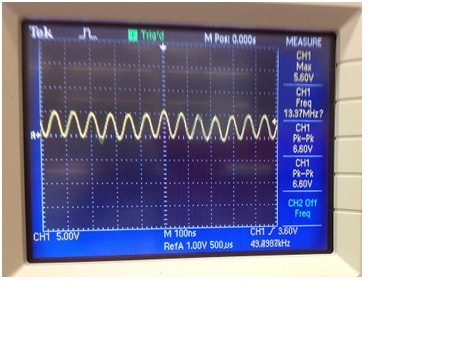
TP1 (6.6Vp-p)

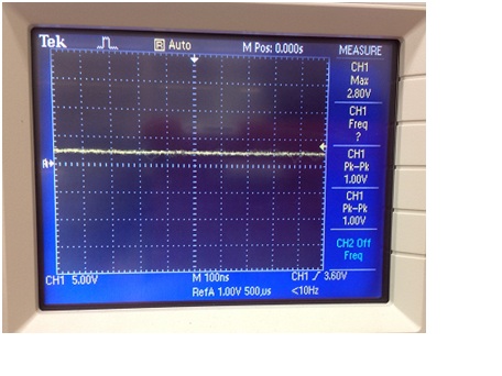
TP2 (after crossing the inductor 169nH, it seems like the signal is filtered out, only noise remains. It’s very strange)

TP4 (PA drain, the voltage is always around 9.4V, it seems like the FET does not operate).

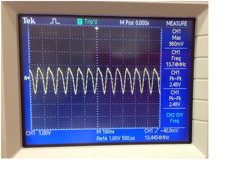
TP7 (output voltage, only 2.48Vp-p)

In addition, when I measured the output voltage of the regulator 7812, the value is only 8.5V instead of 12V. So could you please look at my problem and give me some advice?

Regards,

Tuan


  • Hi I have meet the same problem that the Vp-p is approximately 2.5v when connect the reader with the amplifier.

    I just use the LM1085 and IRF510 (same as the document mentioned).

    To Tuan:

       your second problem (7812 measured 8.5v) may caused by the power supply. it needs 15v and not less than 1Amp to support the circuit.

    I've just encountered the problem last week when I use a 600mA supplier. >_<


  • Hello,

    I am also working with the same power amplifier schematic, and I chanced upon this post.

    I have a question regarding the received signals RX_1 and RX_2.

    During the time when the reader transmit is active, the signal levels at RX_1 and RX_2 reaches about 10Vp-p signal levels.

    According to the trf7960a datasheet, RX_1 and RX_2 should have a maximum rf input voltage equal to Vin (~3.4 V).

    Does it not cause a problem that when transmitting, the RX_1 and RX_2 ports encounters voltage levels of ~10V peak?

    Thanks!

    Regards,

    Roman Lorenzo A. Balayan

  • Hi Roman

    The input voltage of the RX_1 and RX_2 should not reach ~10V, but instead you should see a demodulated signal for the input. The combination of the diode and the capacitors makes a demodulation, which also reduces the voltage.

    It's some time ago, that you wrote the message - have you solved the problem in the mean time?

    Regards Henrik