This thread has been locked.

If you have a related question, please click the "Ask a related question" button in the top right corner. The newly created question will be automatically linked to this question.

CC1120 sync detect on carrier from second CC1120

Other Parts Discussed in Thread: CC1120, CC1020

Hi,

I have a legacy design which I am changing from CC1020 to the CC1120. 

The system consists of a wireless master (Panel) which communicates to several wireless slaves (Devices).

Messages can be exchanged as follows:

Panel can talk to Devices; Devices can talk to the Panel; Devices not allowed to talk to each other. 

The nature of the protocol and existing software suggests I use sync. serial mode.

RF setup is 9600 Baud, GFSK @ 868MHz. 
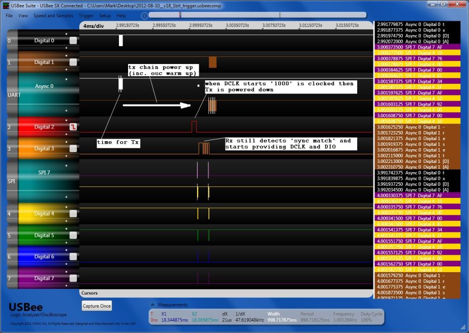
Tx mode:

- Tx enabled in synchronous serial mode (Message data is transferred using GPIO's configured as DCLK and DIO).

- CC1120 provides DCLK when Tx carrier is up, external mcu uses this to clock in the preamble followed by sync word and payload. 

Rx mode:

- Rx enabled in synchronous serial mode with sync word detection.

- CC1120 only provides DCLK and DIO when it finds a sync word match. 

- Dual sync search is used. (0xCCF0 and 0xAAF0).

- Preamble detect is not used as there are two preamble types in use 0xCC , 0xAA.

Devices were converted over to use the CC1120 without issue.

CC1120 to CC1020 comm's works fine both ways. 

When the Panel was upgraded to use the CC1120 something strange started happening....

- Panel puts its CC1120 in to the rx mode described above (i.e. DCLK and DIO are idle since it is waiting for a sync word match)

- Panel expects that when the CC1120 starts providing DCLK that a sync detect has occured and starts reading in the payload. 

Case A:

- When a Device fitted with CC1020 starts transmitting the Panel CC1120 detects a sync word match at the appropriate point and starts providing DCLK and DIO. 

- Panel reads in the payload, works fine. 

Case B:

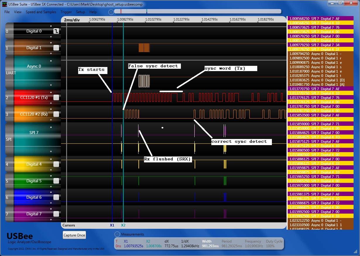
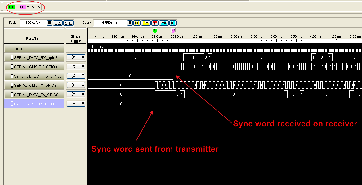
- When a Device fitted with CC1120 starts transmitting then Panel CC1120 detects a sync word match within 700us of the transmitting CC1120 providing DCLK (i.e. pretty much as soon as the transmitting device's carrier going up).

- Panel reads in DCLK and DIO thinking it is the payload  (when it is actually the preamble).

- Panel rejects this as a mis-formatted message and restarts the search. By which time it has missed the actual message.

- This problem exists both ways Panel Tx >>> Device Rx  and Device Tx >>> Panel Rx. 

My questions:

- Has anyone seen this false sync word lock when the carrier from another CC1120 goes up?

- Any ideas what I'm doing wrong or how to solve this problem?

Mark.

  • Hi Mark

    Have you tried to change the sync threshold (SYNC_CFG1.SYNC_THR) to a stricter threshold? With the sync words you are using the first 8 bis are identical to the preamble so it sounds to me that the threshold is to loose which causes you to get sync detect on the preamble. Does case B happen for both sync words?

    If you can provide the register settings for the CC1120 it would be helpfull.

  • Hi Martin,

    Thank you for getting back to me.

    The sync detect is not triggering on the preamble it triggers as soon as the carrier comes up. 

    Maybe it is better put like this:

    CC1120 #1 is the Tx

    CC1120 #2 is the Rx

    If I put a scope on the data going into #1 while it is transmitting, and another probe on the data coming out of #2 while in RX I see ~ 750us propegation delay.

    The sync detect on #2 fires ~ 750us after the #1 starts transmitting. i.e. as soon as the first bit (not bits) of preamble hits the rx demod stage.

    I've attached a screen shot:

    This consistantly occurs at the same instant every time the Tx carrier comes up.

    The above signal was at -109 dBm and AGC_CS_THR was set to 0 (i.e. -100dBm), so I doubt it is carrier detect causing a problem (not sure how carrier sense could force a sync match though?)

    I'll get a register listing posted tomorrow.

    Mark.

  • I'll also try just sending out 1 bit of carrier and see what happens.

  • I setup the same test. This time the Tx alternates between sending a message, then next time round just sending 1 bit (a '1') followed by 3 '0' then turns off the tx chain.

    Same false trigger occurs, so its definatly something to do with the CC1120 triggering on the carrier coming up. 

  • Register Listing for Synchronous serial Rx with sync detect. (i.e. DCLK & DIO only after sync word found)

    following values were read back while the device was in synchronous serial mode, with 2x 16bit sync search. enabled. 

    extern const uchar CC1120_initialise_00_2E[] = {

    Read back of registers 0x00 to 0x2E:


    0x08, // IOCFG3 GPIO3 IO pin configuration register.
    0x17, 0x31 // IOCFG2 GPIO2 IO pin configuration register.
    0xB0, 0x06 // IOCFG1 GPIO1 IO pin configuration register.
    0x09, // IOCFG0 GPIO0 IO pin configuration register.
    0xCC, // SYNC3 Sync word programming (31:24).
    0xF0, // SYNC2 Sync word programming (23:16).
    0xAA, // SYNC1 Sync word programming (15:8).
    0xF0, // SYNC0 Sync word programming (7:0).
    0x0B, // SYNC_CFG1 Sync Word Detection Programming
    0x1C, // SYNC_CFG0 Sync Word Length Programming
    0x41, // DEVIATION_M Frequency Deviation Programming
    0x0B, // MODCFG_DEV_E Modulation Format and Frequency Deviation Programming
    0x1C, // DCFILT_CFG Digital DC removal Programming
    0x03, // PREAMBLE_CFG1 Preamble Length Programming
    0x2A, // PREAMBLE_CFG0 Preamble Detection Programming
    0x40, // FREQ_IF_CFG RX Mixer Frequency Programming
    0x80, // IQIC Digital Image Channel Compensation Programming
    0x07, // CHAN_BW Channel Filter Programming
    0x06, // MDMCFG1 General Modem Parameter register.
    0x0A, // MDMCFG0 General Modem Parameter register.
    0x73, // DRATE2 Symbol Rate Programming Exponent and Mantissa (19:16).
    0xA9, // DRATE1 Symbol Rate Programming Mantissa (15:8).
    0x2A, // DRATE0 Symbol Rate Programming Mantissa (7:0).
    0x36, // AGC_REF AGC Reference Level
    0x00, // AGC_CS_THR Carrier Sense Threshold Programming
    0x00, // AGC_GAIN_ADJUST RSSI Offset Programming.
    0x91, // AGC_CFG3 AGC Programming
    0x20, // AGC_CFG2 AGC Programming.
    0x09, // AGC_CFG1 AGC Programming
    0xCF, // AGC_CFG0 AGC Programming
    0x00, // FIFO_CFG
    0x00, // DEV_ADDR
    0x03, // SETTLING_CFG
    0x12, // FS_CFG
    0x08, // WOR_CFG1
    0x21, // WOR_CFG0
    0x00, // WOR_EVENT0_MSB
    0x00, // WOR_EVENT0_LSB
    0x05, // PKT_CFG2
    0x00, // PKT_CFG1
    0x20, // PKT_CFG0
    0x0F, // RFEND_CFG1
    0x00, // RFEND_CFG0
    0x7F, // PA_CFG2 Power Amplifier Level Programming
    0x56, // PA_CFG1 Power Amplifier Ramp Up/Down Shape Programming
    0x7D, // PA_CFG0
    0x03, // PKT_LEN
    };

    extern const uchar CC1120_initialise_2F00_2F39[] = {

    Read back of registers 0x2F00 to 0x2F39:


    0x00, // IF_MIX_CFG IF MIX configuration
    0x22, // FREQOFF_CFG Frequency Offset Removal programming.
    0x0B, // TOC_CFG Data Rate Offset Removal Programming
    0x00, // MARC_SPARE
    0x00, 0x18 // ECG_CFG
    0x00, // SOFT_TX_DATA_CFG
    0x01, // EXT_CTRL
    0x00, // RCCAL_FINE
    0x00, // RCCAL_COARSE
    0x00, // RCCAL_OFFSET
    0x00, // FREQOFF1
    0x00, // FREQOFF0
    0x6C, // FREQ2
    0x85, // FREQ1
    0x99, // FREQ0
    0x02, // IF_ADC2 Analog to digital converter, reg 2
    0xA6, // IF_ADC1 Analog to digital converter, reg 1
    0x04, // IF_ADC0 Analog to digital converter, reg 0
    0x00, // FS_DIG1
    0x5F, // FS_DIG0
    0x00, // FS_CAL3
    0x20, // FS_CAL2
    0x40, // FS_CAL1
    0x0E, // FS_CAL0
    0x28, // FS_CHP Charge pump
    0x03, // FS_DIVTWO Divide by 2
    0x00, // FS_DSM1 Digital synthesizer module, reg 1
    0x33, // FS_DSM0 Digital synthesizer module, reg 0
    0xFF, // FS_DVC1 Divider chain, reg 1
    0x17, // FS_DVC0 Divider chain, reg 0
    0x00, // FS_LBI Local bias
    0x50, // FS_PFD Phase-frequency detector
    0x6E, // FS_PRE Prescaler
    0x14, // FS_REG_DIV_CML
    0xAC, // FS_SPARE
    0x14, 0x10 // FS_VCO4 Voltage controlled oscillator, reg 4
    0x00, // FS_VCO3 Voltage controlled oscillator, reg 3
    0x00, // FS_VCO2 Voltage controlled oscillator, reg 2
    0x00, // FS_VCO1 Voltage controlled oscillator, reg 1
    0xB4, // FS_VCO0 Voltage controlled oscillator, reg 0
    0x00, // GBIAS6 Global bias, reg 6
    0x02, // GBIAS5 Global bias, reg 5
    0x00, // GBIAS4 Global bias, reg 4
    0x00, // GBIAS3 Global bias, reg 3
    0x10, // GBIAS2 Global bias, reg 2
    0x00, // GBIAS1 Global bias, reg 1
    0x00, // GBIAS0 Global bias, reg 0
    0x01, // IFAMP Intermediate frequency amplifier
    0x01, // LNA Low noise amplifier
    0x01, // RXMIX RX mixer
    0x0E, // XOSC5 Crystal oscillator, reg 5
    0xA0, // XOSC4 Crystal oscillator, reg 4
    0x03, // XOSC3 Crystal oscillator, reg 3
    0x04, // XOSC2 Crystal oscillator, reg 2
    0x03, // XOSC1 Crystal oscillator, reg 1
    0x00, // XOSC0 Crystal oscillator, reg 0
    0x00, // ANALOG_SPARE
    0x00, // PA_CFG3
    };

    Read back of 0x2F91:

    0x00 0x02 // SERIAL_STATUS

  • I wasn't 100% sure that the above values were correct so I changed the code to do a dump of the register values during sync serial Rx mode with sync detect enabled., 

    The corrections I found are highlighted in yellow above. 

    I'm still seeing the problem of the sync word detect triggering when another CC1120 carrier comes up. 

    Please help!

  • Hi Mark

    I briefly looked over your register settings and they look OK. I will test your settings on our HW to see if I'm able to reproduce this issue and get back to you ASAP.

  • Hi Martin,

    Interestingly it doesn't happen whan a CC1020 carrier comes up.

    Very strange.....

  • Hi Mark

    I have tested your settings on our HW and this works perfectly. The attached picture shows that the receiver does not start to output data or clock signal until the sync word is received. Since the CC1120 receives correctly from the CC1020, it sounds to me that the issue might be on the tx side. Can you do a similar plot as I did with the PKT_SYNC_RXTX signal (GPIOx_CFG = 0x06) output on one of the GPIO's for both TX and RX?

  • I think you might have hit it there. 

    My guess is that this is happening:

    - MCU issues STX to CC1120.

    - CC1120 sends out sync word (automatically) then starts providing DCLK.

    - MCU on receiving DCLK, clocks out preamble then sync then payload. 

    - Receiving CC1120 sees the first sync and starts providing DCLK. 

    I'll check PKT_SYNC_RXTX and post back.

  • Mark

    When you use synchronous serial word on the CC1120 it automatically sends preamble and sync word before the serial data is sent (assuming SYNC_CFG0.SYNC_MODE is different from zero). This means that the MCU only has to provide the payload over the serial data line. If you sends additional preamble and sync word from the MCU the receiving CC1120 will already have found sync on the first sync word sent from the radio.

  • Hi Martin,

    I set SYNC_CFG0 to 0x00 before STX. Then back to 0x1C before SRX.

    i.e.

    - in Tx mode the CC1120 will provide DCLK as soon as the carrier is up. I then send the preamble, sync and payload using DCLK and DIO. 

    - in Rx mode the CC1120 will not provide DCLK until one of two 16bit sync words is found. I then send an SRX when I have clocked in enough data and want to go back to sync word searching. 

    All works fine now. Many thanks for your help on this. 

    Mark. 

  • Hi Mark.

    If you want you can let the CC1120 do the preamble and sync automatically. You then have to remove them from the DIO.However your approach works just as good, especially if you want the SW to be the same for both the CC1120 and the CC1020.

    Anyway, its great news that you have everything up and running. Good luck going forward