This thread has been locked.

If you have a related question, please click the "Ask a related question" button in the top right corner. The newly created question will be automatically linked to this question.

Wireless M-Bus and CC1120 in 169 MHz, Is it posible?

Other Parts Discussed in Thread: CC1120, WMBUS

Hi All,

I have been reading about that, and also i have the CC1120 eval modules with an MSP430.

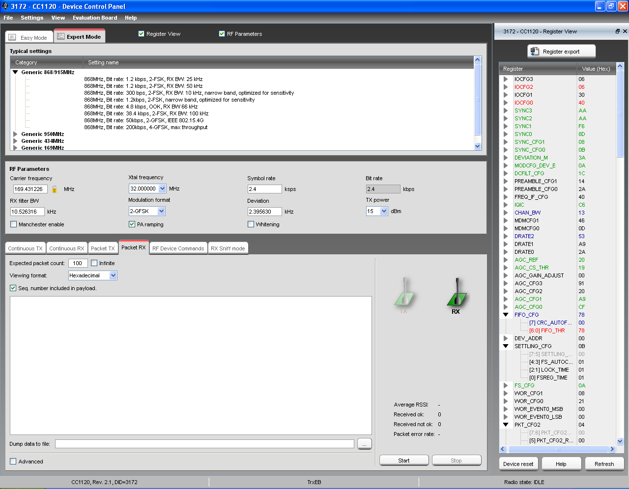
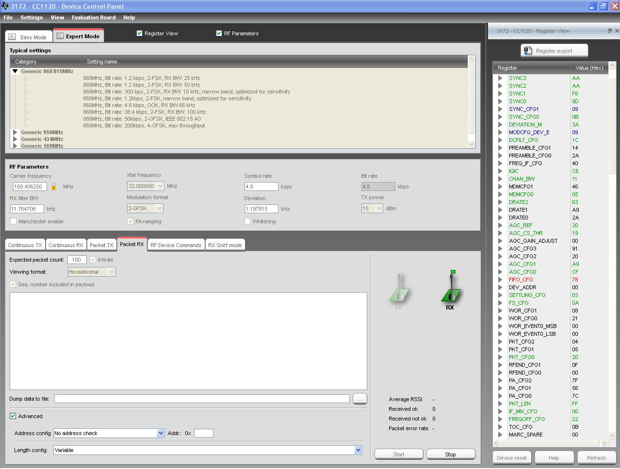
The CC1120 it works in 169 MHz, and i could send messages from one to other device. The problem it is to configure to work with other devices over the wireless m-bus standard, I try to configure the registers to meet with the standard but I am not able to solve it. In the website of TI (http://www.ti.com/lit/ml/slyt433/slyt433.pdf) there are several pdfs and other stuffs telling that it is posible, but all the developments are for 868 MHz.

So Anyone could help me with this? I also know there are other solutions from Radocrafts, amber-wireless, and more ones, but i really want to try with CC1120.

Many Thanks in advance.

Maykel

  • CC1120 supports WMBUS N without any problems. See the attached Excel shhet for register settings.7142.WMBUS_N_settings.xlsx

  • Hi TER,

    I tried with teh settings you gave me and doesn´t work.

    For the test I use the SmartRF Studio with the cc112xEM module and an eval board from Telit for communications in wM-Bus. The Telit eval board I configure for channel 1a as the table below and I send typical messages:

    Channel Carrier Frequency (MHZ) Modulation Bit-Rate (kbps) Channel Bandwidth (kHz) Deviation (kHz) Max Power Output (mW)
    1a 169,40625 GMSK 4,8 12,5 1,2 500

    The registers I put as the ones for N1a mode from your spread sheet, and I put this frequency register values:

    FS_CFG = 0x0A

    FREQ2 = 0x69

    FREQ1 = 0xE1

    FREQ0 = 0x00

    Attached it is a capture for the smartRF Studio, using the Packet RX utility.

    The result it does not work. I also tried to change parameters for the paket length and CRC, and also doesn´t work.

    Any Idea to solve this? Am I doing something wrong?

  • You have used N1c mode in the SmartRF Studio but the Telit unit uses the old N1a. Please note that the deviation is changed to 2.4kHz in this mode. What you have to do is to use the N1a settings I provided and change the deviation to 1.2kHz. The datarate and deviation have to be the same on both sender and receiver.

  • Hi TER and thanks again. I tried with the register values you provided me for N1a, and changed the deviation to 1.2 kHz (MODCFG_DEV_E = 0x09) as you told me. It continues without working. There are other registers that i have to configure. The ones I have changed are:

    PKT_CFG0= 0x20 --> Give variable length, the first byte after the sync word it is the length

    PKT_LEN= 0xFF  --> Max value of the packet length

    FS_CFG=0x1A; FREQ2= 0x69; FREQ1=0xE4;FREQ0=0xFF --> Frequency of 169.40625 MHz

    Here iti is a capture of the SmartRF Studio and also I attached a document 

    // Rf settings for CC1120
    RF_SETTINGS code rfSettings = {
        0xB0,  // IOCFG3               GPIO3 IO Pin Configuration
        0x06,  // IOCFG2               GPIO2 IO Pin Configuration
        0x40,  // IOCFG0               GPIO0 IO Pin Configuration
        0xAA,  // SYNC3                Sync Word Configuration [31:24]
        0xAA,  // SYNC2                Sync Word Configuration [23:16]
        0xF6,  // SYNC1                Sync Word Configuration [15:8]
        0x8D,  // SYNC0                Sync Word Configuration [7:0]
        0x09,  // SYNC_CFG1            Sync Word Detection Configuration
        0x0B,  // SYNC_CFG0            Sync Word Length Configuration
        0x3A,  // DEVIATION_M          Frequency Deviation Configuration
        0x09,  // MODCFG_DEV_E         Modulation Format and Frequency Deviation Configuration
        0x1C,  // DCFILT_CFG           Digital DC Removal Configuration
        0xC6,  // IQIC                 Digital Image Channel Compensation Configuration
        0x11,  // CHAN_BW              Channel Filter Configuration
        0x05,  // MDMCFG0              General Modem Parameter Configuration
        0x63,  // DRATE2               Data Rate Configuration Exponent and Mantissa [19:16]
        0x20,  // AGC_REF              AGC Reference Level Configuration
        0x19,  // AGC_CS_THR           Carrier Sense Threshold Configuration
        0xA9,  // AGC_CFG1             AGC Configuration
        0xCF,  // AGC_CFG0             AGC Configuration
        0x78,  // FIFO_CFG             FIFO Configuration
        0x03,  // SETTLING_CFG         Frequency Synthesizer Calibration and Settling Configuration
        0x0A,  // FS_CFG               Frequency Synthesizer Configuration
        0x20,  // PKT_CFG0             Packet Configuration, Reg 0
        0xFF,  // PKT_LEN              Packet Length Configuration
        0x00,  // IF_MIX_CFG           IF Mix Configuration
        0x22,  // FREQOFF_CFG          Frequency Offset Correction Configuration
        0x69,  // FREQ2                Frequency Configuration [23:16]
        0xE1,  // FREQ1                Frequency Configuration [15:8]
        0x3F,  // FS_CHP               Charge Pump Configuration
        0x1F,  // FS_VCO4              VCO Configuration, Reg 4
        0x1C,  // FS_VCO1              VCO Configuration, Reg 1
        0x01,  // DCFILTOFFSET_I1      DC Filter Offset I (MSB)
        0x72,  // DCFILTOFFSET_I0      DC Filter Offset I (LSB)
        0xF5,  // DCFILTOFFSET_Q1      DC Filter Offset Q (MSB)
        0xC8,  // DCFILTOFFSET_Q0      DC Filter Offset Q (LSB)
        0xFB,  // IQIE_I1              IQ Imbalance Value I (MSB)
        0x53,  // IQIE_I0              IQ Imbalance Value I (LSB)
        0xFE,  // IQIE_Q1              IQ Imbalance Value Q (MSB)
        0x6C,  // IQIE_Q0              IQ Imbalance Value Q (LSB)
        0x08,  // RSSI1                Received Signal Strength Indicator (MSB)
        0x63,  // RSSI0                Received Signal Strength Indicator (LSB)
        0x01,  // DEM_STATUS           Demodulator Status
        0xFF,  // FREQOFF_EST1         Frequency Offset Estimate (MSB)
        0xD8,  // FREQOFF_EST0         Frequency Offset Estimate (LSB)
        0x1B,  // AGC_GAIN3            AGC Gain, Reg 3
        0xA3,  // AGC_GAIN2            AGC Gain, Reg 2
        0x1B,  // AGC_GAIN1            AGC Gain, Reg 1
        0xD1,  // MAGN0                Signal Magnitude after CORDIC [7:0]
        0x03,  // ANG1                 Signal Angular after CORDIC [9:8]
        0x2C,  // ANG0                 Signal Angular after CORDIC [7:0]
        0x08,  // CHFILT_I0            Channel Filter Data Real Part [7:0]
        0x07,  // CHFILT_Q2            Channel Filter Data Imaginary Part [18:16]
        0xFF,  // CHFILT_Q1            Channel Filter Data Imaginary Part [15:8]
        0xB0,  // CHFILT_Q0            Channel Filter Data Imaginary Part [7:0]
        0x48,  // PARTNUMBER           Part Number
        0x21,  // PARTVERSION          Part Revision
        0x11,  // RX_STATUS            RX Status
    };
    with all the values for the register.

    What is it wrong? Maybe the modulation, because the Telit module uses GMSK and in the SmartRF Studio it is 2-GFSK. 

    Any other idea?

    Many Thanks.

  • In this case a fairly narrow RX bandwidth is used. It is likely that you have a frequency offset in your system that cause the signal to be (partially) outside the RX filter.

    Try to increase the RX bandwidth to above 25kHz. Also measure the frequency on both the sender and receiver and compensate for the difference in Studio.

  • Hi TER,

    I have increase the Rx Bandwidth to 25 kHz first, and the to 33 kHz (Max Allowed). There is not result.

    I have measured in an spectrum analyzer the output signal of the channel 1a of the telit module and the frequency center peak is always betwen the 169.4053-169.4078 MHz, with a signal of -33 dBm in the antenna connector, so I think it is OK. The bandwidth of the signal measured at -3 dB it is of 15 KHz (from 169.400100 MHz to 169.41600 MHz) and the bandwidth of the signal measured at -80 dBm (50 dBm difference) it is from 169.35600 MHz to 169.46100 MHZ.

    As I tell you before, the modulation is different in the cc1120 it is 2-GFSK and in the Telit it is GMSK. I put here a capture for the Functional characteristic of the Telit module.

    Any idea more? Thanks for your help.

  • Do you know if you are sending frame format A or B?

    Note that the SYNC word is 0xF68D for format A and 0xF672 for B.

    It could also be interesing if you set sync to 0xAAAA to see if you get something into the RX buffer then.

  • I'm sending frame format A, but I think in wM-Bus for 169 MHz (EN 13757-4:2010) , there is not sync word. My frame as far as I know is like:

    PREAMBLE | BLOCK 1 | BLOCK 2 | ...

    In the case of Mode N, the preamble for GFSK and GMSK it is 4 bytes (channels 1a, 1b, 2a, 2b, 3a, 3b) and for 4-GFSK it is 8 bytes (channel 0).

    Then the block 1 consists in the Length, Control, Manufacturer id, Address id and CRC. The block 2 has the Control information and the data, tah could continue in next blocks.

    I tried with configuring no syncword and with the preamble of 4 bytes with the different types, and does not work.

    SYNC_CFG0 = 0x03 --> No sync word

    PREAMBLE_CFG1 = 0x18 --> 4 bytes of 0xAA

    Also I tried changing the SYNC word to 0xAAAA, and nothing.

    What next?

  • Hi Maykel,

    for M-Bus communication, you always have to use a sync word and a preamble. CC1120 is very strong on synchronizing, so 2 bytes of preamble should absolutely work for TrxEB + CC1120EMK. But first, take a look at the correct frequency. The channels are really narrow. Use the unmodulated Tx in SmartRf Studio to find the offset and enter this in FREQOFF_0 and _1. Make further sure to use 0x55 as preamble. Former implementations were more "relaxed" on sync word errors, while this lead to many faulty received packets.

    Regards, Dirk

  • We do confirm : We have developed several CC1120-based products working in the 169MHz band (500mW output power using a discrete low cost amplifier), and had no problem at all to interoperate with off-the-shelf EN13757-4 modules like Telit's. Contact us if you need any help in your design.

    Friendly yours,

    Robert Lacoste - www.alciom.com - TI's low power RF design partners

  • If you need up to +30 dBm (1 W) RF output power, I invite you also to consider alternatives like the EMB-WMB169PA: http://www.embit.eu/products/wireless-modules/emb-wmb169pa/ . It is based on the CC1120 and operates in the 169 MHz band... moreover it is compliant with the very latest standard: EN 13757-4:2013 

    Hope this helps,

    Francesco