This thread has been locked.

If you have a related question, please click the "Ask a related question" button in the top right corner. The newly created question will be automatically linked to this question.

TRF7970A Low Power gives higher received signal strength (RSSI)?

Other Parts Discussed in Thread: TRF7970A

Hi,

I've got a TRF7970A EVK board connected to a coil through the SMA connector, and I am using the RSSI level in Reg0x0F to evaluate coil read range. I've placed an RFID tag in the centre of the coil and I am monitoring the RSSI level.

When running at Full power, my Main and Aux RX strength are 5 and 0 respectively.  Using Half power, my Main and Aux RX strength are both 5.

This seems counter-intuitive, so what else is going on?

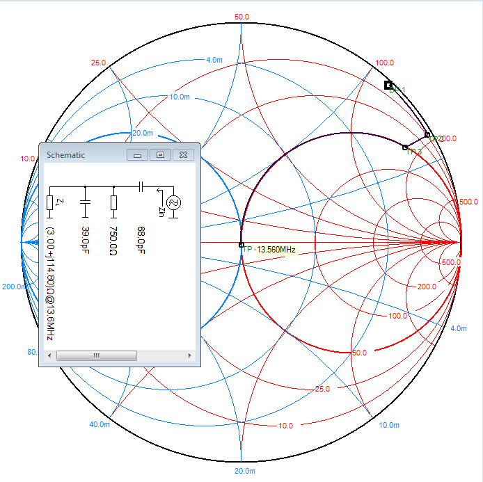
I guess that if my coil is does not have a characteristic impedance of 50ohms, then the 4-50ohm impedance matching circuit will behave differently - giving an overall better power transfer when the output impedance is 8ohms? What do you guys think?

Stephen

  • Stephen -

    You did remove R3, corrrect (to disconnnect the onboard antenna ckt?) if not that could be one area to take care of and then also, when you say your coil - you do mean your tuned coil, correct? (meaning you are providing your own series and shunt elements, with a Q factor appropriate for the tag technology you are using)


  • Josh,

    R3 has been removed.

    I measured the coil in isolation to have an impedance of 3+114.8j. Used a shunt resistor of 750R, shunt cap of 69pf, and series cap of 39pf. Then I connected the coil through a Skyworks switch, so I can connect multiple coils. I should have a Q of 6.5 and a bandwidth of 2.08MHz.

    I've measured the tuned coil through the switch to have a characteristic impedance of around 44ohms. I've got a transmission line that goes through the switch and then can get terminated with my calibration load - that gives |z| of 54R.

  • I agree that you R should be around 750 ohms here for that Q factor, however, i plotted out your tuning solution on the Smith Chart and i think you should adjust it the other way round.

    your shunt cap (in parallel with the R and the coil) should be 39pF and the series element should be 68pF. pls.check that out.

  • Josh,

    Sorry about that, I meant I had series cap of 69pF and a shunt cap of 39pF like you've shown.

  • Right - so the best to do - if you have a power meter or spectrum analyzer - is to hook it up (using attenuators if needed by the instrument so you don't damage it) and measure like what i have shown in this document (using the Peregrine digital switches) and see if you can get some more data about what is going on with your ckt.

    http://www.ti.com/litv/pdf/sloa167 (section 5)

    i have built several of these units and been able to replicate good performance and get back expected RSSI values.

    See video here of the smaller four channel version here ==> http://www.youtube.com/watch?v=16VFU9n8VO4&feature=plcp

  • Josh,

    I've got a PSA1301T 1.3GHz Spectrum Analyzer. Its a handheld unit, but I dont know if it is any good.

    It's got a max input power of +20dBm and ±15VDC. I dont have any attenuators, but if I run the TRF7970A at 3v3 and half power then I should be OK (14dBm).

    In which case do I just connect the spectrum analyzer to the output port of my switches?

    EDIT:

    I didnt want to blow anything up, so I am using a near field prob instead. I've positioned the probe near one of the coils. I can see a spike at 13.56 MHz, at approx -22dBm for Half Power, and -19dBm for Full Power.