This thread has been locked.

If you have a related question, please click the "Ask a related question" button in the top right corner. The newly created question will be automatically linked to this question.

cc1125 spi

Other Parts Discussed in Thread: CC1125

Hello,

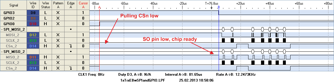
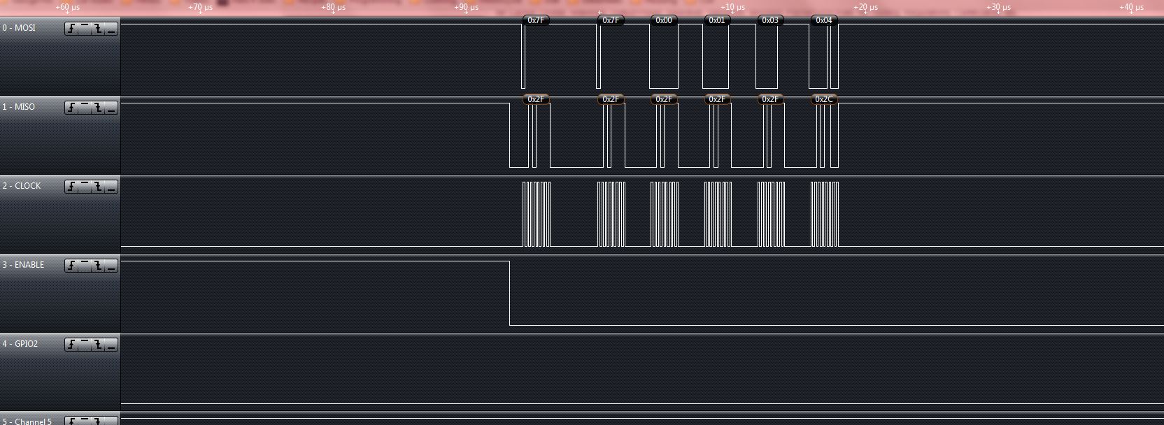
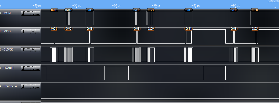
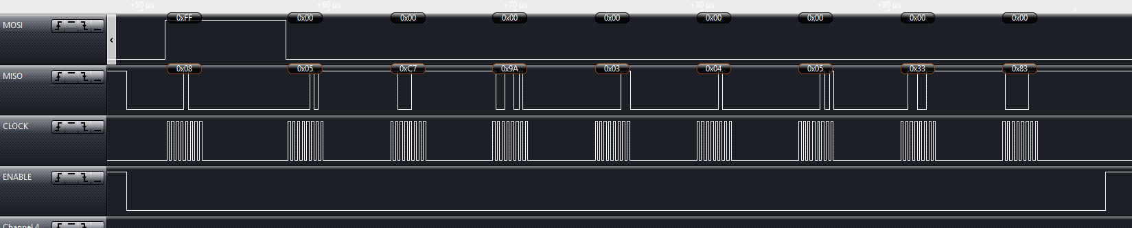
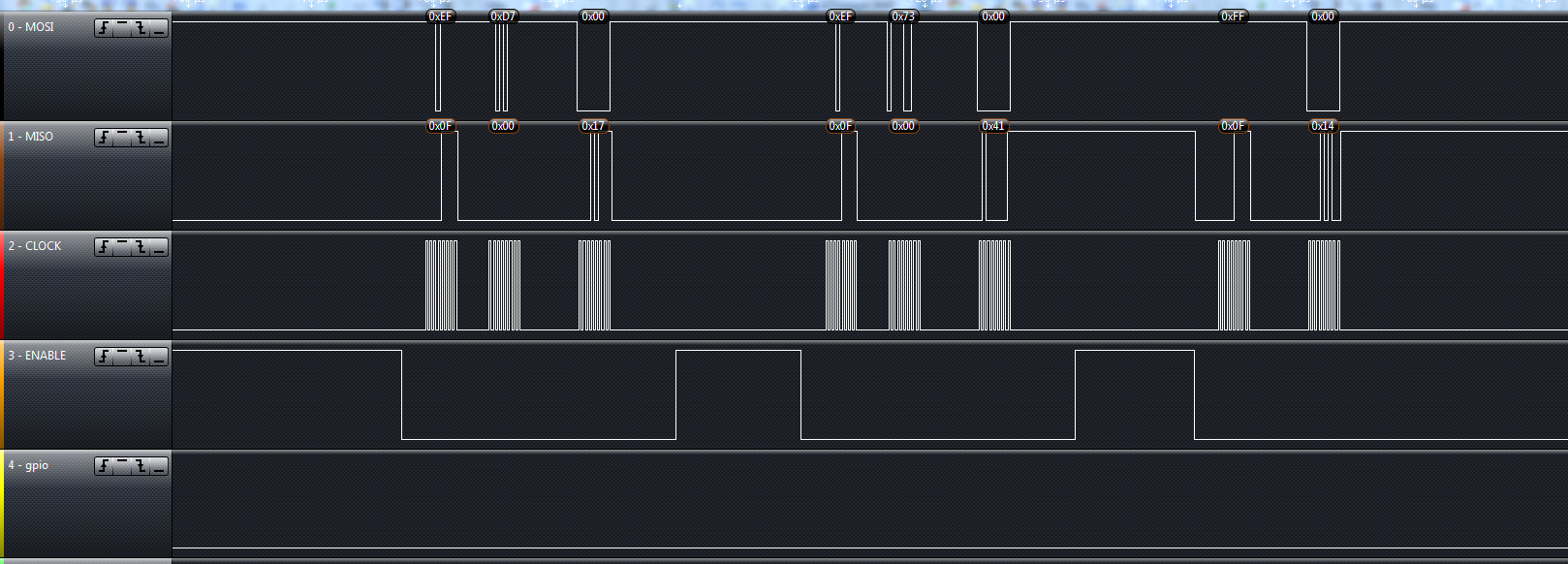
I'm trying to connect my own MCU to the CC1125 via its evaluation board. I believe that I have everything wired together properly. What I need help with is some of the SPI stuff. I ran the cc112x_easy_link software with the evaluation boards MPS430 mcu and I used a logic analyzer on the SPI bus, then I wrote the software for my MCU and ran it on the SPI bus and compared the two. My timing diagram is nearly identical, however I'm getting different status values back from the CC1125. I'm seeing that the mps430 gets back a status byte of 0x7F for each write command. Mine however is getting decremented values that stay between 0x7F and 0x70, cycling over and over again. (I've attached images for reference).

What status values should I be getting? 0x7F?

  • Hi Jason

    The returned status byte you are getting indicates a TXFIFO error condition. Have you done any TX operations before this plot? When debugging SPI communication I would recommend being in a known state (IDLE).  After a fresh reset of the chip and being in IDLE state the returned status byte should be 0x0F when you write to the radio and 0x00 when you read from the radio. 

  • I just did another logic capture and I think I have more specific information to share. I start off by initializing all of my registers. For the first two registers that I transmit to, I get back a status bytes of 0xFF, these are returned at the same time, so should each refer to the previous transmission to line them up? The remaining registers all transmit properly returning a status byte of 0x0F for each one. Once I get into the extended registers, each of the three bytes receives a status byte pattern of 0x0F 0x00 0x0F.

    Then I begin a FIFO burst access of 30 bytes. Each byte receives a status byte returned of 0x0F. CSn is brought back high, then I drop it low again and command strobe 0x35 to flush the FIFO. When I send the flush command, the byte that is returned at the exact same time is 0x0F (again, is that for the command at the same time or the previous command?). Then when I go to begin another 30 byte transmission, every single status byte that I receive is 0x5F for the second packet. Then when it goes to send another 30 packets, the received status bytes are all 0x2F. Then the status bytes start decrementing and are all different.

    Any idea where the error is happening and how to debug it?

    Thanks!

  • Hi Jason

    First of all, the status bytes indicates the actual state the radio is in when the CSn line is pulled low and does not relate to the previous command ( except when altering radio states). If you issue multiple command strobes the status byte will not change until the actual radio state has changed (see the data sheet for transition times).

    When you get a status byte of 0xFF, this tells me that the radio is not ready (CHIP_RDYn bit is high) when you write to the chip. When you wake the chip up from powerdown or just turned the chip on, the crystal needs time to start up and stabilize. When the crystal is stable the chip is ready for operation and you can start to write or read to it.This is indicated by the CHIP_READYn bit or the SO line which when you pull CSn low the SO line will stay high until the chip is ready. If you try to read or write to the chip before it is ready you can get unknown results. A proper write sequence after wake up from power down can be seen in the following plot:

    Jason Kelly1 said:

    Then I begin a FIFO burst access of 30 bytes. Each byte receives a status byte returned of 0x0F. CSn is brought back high, then I drop it low again and command strobe 0x35 to flush the FIFO. When I send the flush command, the byte that is returned at the exact same time is 0x0F (again, is that for the command at the same time or the previous command?). Then when I go to begin another 30 byte transmission, every single status byte that I receive is 0x5F for the second packet. Then when it goes to send another 30 packets, the received status bytes are all 0x2F. Then the status bytes start decrementing and are all different.

    This will be normal behaviour. If you fill the TXFIFO with 30 bytes and strobe 0x35 (BTW this is a STX strobe not a TXFIFO flush which is 0x3B) you will get a status byte indicating IDLE state (0x0F). When you then start to fill the TXFIFO with more data, the radio will return a status byte of 0x5F indication SETTLING state. The radio is now going from IDLE to TX as stated by the STX strobe you sent. For the next 30 bytes you write the radio has come into TX state and indicates this by a status byte of 0x2F.

    The F part indicates how many bytes you have free in your TXFIFO (this is undocumented), F indicating 15 or more bytes free.When you continue to fill the TXFIFO this number will decrease as you approach the TXFIFO limit of 128 bytes.

    So in this part there is no error in the status byte as I can see.


  • Martin,

    Thank you, that timing diagram was very helpful. I've added a while statement that waits for MISO to drop low and the results have made me confident that the first few registers that are being sent are being received.

    As for sending the STX command(0x35), this is what I want isn't it? Essentially I want to be continuously sending data packets from one cc1125 transceiver to another. When I send the STX command, does it transmit what is in the FIFO buffer, and then clear it? Do I need to do any other housekeeping, or have I basically stubbed out the whole process for transmission?

  • After I sent the STX command, do I need to wait for GPIO2 to interrupt and let me know that the data has been transmitted over RF before I can send another packet?

  • Hi Jason

    When you issue the STX strobe the radio will start to send preamble, sync word and then the content of the TXFIFO. The TXOFFMODE (RFEND_CFG0) sets the state the radio continues to after transmission. As default the radio will go to IDLE after the last byte is sent.

    To know that the packet is sent and the radio is ready for next transmission you can either wait for a PKT_SYNC_RXTX de-assertion (interrupt on one of the GPIO's) or you can poll the MARCSTATE register and wait for the radio to enter IDLE mode.

    In CC120X_Software_examples the transmitter waits for the interrupt before it continues with the next packet.

  • Now after the last byte has been sent, is the best state to remain in idle, in order to send successive packets? Do I need to flush the FIFO after a transmission?

    Thanks for your help.

  • Hi

    There is no need to flush the TXFIFO as long as the packet has been sent successfully. If you want to send successive packets I would recommend to have the TXOFFMODE= TX so the radio stays in TX.This will reduce the turn around time used going from TX to IDLE to TX for each packet.  Then you can just fill the FIFO with the new packet as soon as the preceding packet has been sent.

    This can be done in the following way:

      // Set TXOFFMODE = TX
      uint8 writeByte = 0x20;
      cc112xSpiWriteReg(CC112X_RFEND_CFG0, &writeByte, 1);
      // Strobe TX
      trxSpiCmdStrobe(CC112X_STX);
      //Continiously sent packets until button is pressed
       {
        
        // Write packet to tx fifo
        cc112xSpiWriteTxFifo(txBuffer,sizeof(txBuffer));
           
        // Wait for interrupt that packet has been sent.
        // (Assumes the GPIO connected to the radioRxTxISR function is set
        // to GPIOx_CFG = 0x06)
        while(!packetSemaphore);
       
        // Clear semaphore flag
        packetSemaphore = ISR_IDLE;  
       
      }while(!halButtonsPushed());
     
      // Button pushed, strobe IDLE
      trxSpiCmdStrobe(CC112X_SIDLE);

  • About how long should it take for the data to be transmitted? I'm clocking about 40 ms before the GPIO2 line interrupts.

    My MCU seems to stop doing SPI while it's waiting; once the GPIO2 pin comes back up, then my SPI will transmit maybe a couple bytes and then just cut off. never to transmit again.

    I tried polling MARCSTATE but I'm not sure if I'm reading data correctly.

    The GPIO2 pin goes high after about 40 ms, then stays high for 300 ms; is this accurate?

  • When the transceiver is "settling" does that mean it is transmitting? For instance, if I am getting a status byte of "settling", when that returns to "TX mode", does that it is done transmitting?

    If the GPIO2 pin is set up for PKT_SYNC_RXTX (0x06), then it should go HIGH when? When the packet has been transmitted? Or when the FIFO is empty? When does it go back low again? Should I only check this pin when sending packets, and not for any register access?

    When I'm in TX mode, do I still need to send the CC112X_STX command...the data sheet leads me to believe that it is to be used in Idle mode. Initially I send the STX command after my first packet...would I still send it after each packet since I would be in TX mode?

  • Hi Jason

    When the tranceiver is in settling state the PLL is settling. This happens between the IDLE and TX state and the radio will not transmit anything before it is in TX.

    The PKT_SYNC_RXTX goes high when the SYNC WORD has been sent and de-asserts when the last byte of the packet is transmitted. The timing of this signal will therefore be dependent of the length of the packet, sync word and the data rate. For more detail on GPIO signals please see section 3.4 of the user's guide

    As long as the radio is in TX there is no need to send any STX commands. The STX strobe is used to set the transceiver in TX and will be ignored if the radio is already in that state. If you are already in TX it is enough to fill the TXFIFO with the next packet for it to be transmitted

  • Ok that is all very helpful.

    Just to make sure that I'm on the right page...according to "Table 2: Status Byte Summary" on of the manual, the upper 4 bits tell me the status of the chip, and I can disregard the lower 4 bits? Or do those lower 4 bits always indicate the amount of space left in the FIFO buffer?

    Once I've sent a packet, I wait until PKT_SYNC_RXTX goes high, and then I continue waiting until it goes low. Once that happens, I begin sending another packet. I've attached a logic capture showing what happens when I do that however. I'm not sure if it is my MCU or not, but I'm noticing that after a couple bytes, the status changes from Tx, to settling, to calibrate, and then to idle, and then SPI comm completely stops with nothing at all happening after that (it doesn't finish the 30 bytes, and then never transmits again). Is the transceiver holding all of my SPI pins high?


    I believe that I'm getting stuck in a while loop that waits for the MISO line to drop low...but it is staying high constantly. So I don't think it is my MCU.

  • You can disregard the lower bytes as they are not guarantied to give you a correct value. From the plot you posted there is something wrong with the transmission but it is hard to tell what can be the cause of this without more information. Could you please post your register settings and a code snippet of your application? This would be of great help to debug this further.

  • Here are my register settings, they are basically copied straight from the example software:

    // Carrier frequency = 868.000000
    // Symbol rate = 1.2
    // Bit rate = 1.2
    // Deviation = 3.997803
    // Manchester enable = false
    // Bit rate = 1.2
    // Modulation format = 2-FSK
    // Bit rate = 1.2
    // RX filter BW = 25.000000
    // TX power = -6
    // PA ramping = true
    // Packet length mode = Variable
    // Whitening = false
    // Address config = No address check.
    // Packet length = 255
    // Device address = 0
    static const registerSetting_t preferredSettings[] = {
    {CC112X_IOCFG3, 0xB0},
    {CC112X_IOCFG2, 0x06},
    {CC112X_IOCFG1, 0xB0},
    {CC112X_IOCFG0, 0xB0},
    {CC112X_SYNC_CFG1, 0x0B},
    {CC112X_DCFILT_CFG, 0x1C},
    {CC112X_IQIC, 0xC6},
    {CC112X_CHAN_BW, 0x08},
    {CC112X_MDMCFG0, 0x05},
    {CC112X_AGC_REF, 0x20},
    {CC112X_AGC_CS_THR, 0x19},
    {CC112X_AGC_CFG1, 0xA9},
    {CC112X_AGC_CFG0, 0xCF},
    {CC112X_FIFO_CFG, 0x00},
    {CC112X_SETTLING_CFG, 0x03},
    {CC112X_FS_CFG, 0x12},
    {CC112X_PKT_CFG1, 0x05},
    {CC112X_PKT_CFG0, 0x20},
    {CC112X_PA_CFG2, 0x4F},
    {CC112X_PA_CFG1, 0x56},
    {CC112X_PA_CFG0, 0x1C},
    {CC112X_PKT_LEN, 0xFF},
    {CC112X_IF_MIX_CFG, 0x00},
    {CC112X_FREQOFF_CFG, 0x22},
    {CC112X_FREQ2, 0x6C},
    {CC112X_FREQ1, 0x80},
    {CC112X_FREQ0, 0x00},
    {CC112X_FS_DIG1, 0x00},
    {CC112X_FS_DIG0, 0x5F},
    {CC112X_FS_CAL0, 0x0E},
    {CC112X_FS_DIVTWO, 0x03},
    {CC112X_FS_DSM0, 0x33},
    {CC112X_FS_DVC0, 0x17},
    {CC112X_FS_PFD, 0x50},
    {CC112X_FS_PRE, 0x6E},
    {CC112X_FS_REG_DIV_CML,0x14},
    {CC112X_FS_SPARE, 0xAC},
    {CC112X_XOSC5, 0x0E},
    {CC112X_XOSC3, 0xC7},
    {CC112X_XOSC1, 0x07},
    {CC112X_RFEND_CFG0, 0x20}, //keeps it in tx, not idle
    };

    My code starts out by setting registers, then it transmits a packet and the STX command; once that happens it enters a loop where it keeps sending packets

    //write radio registers
    registerConfig();

    uint8_t txBuffer[PKTLEN+1] = {0};
    packetCounter = 0;
    uint8_t marcStatus;

    //init packet
    //create a packet with PKTLEN + 2 byte packet counter + n x random bytes
    createPacket(txBuffer);
    // Write packet to tx fifo
    cc112xSpiWriteTxFifo(txBuffer,sizeof(txBuffer));
    // Strobe TX to send packet
    trxSpiCmdStrobe(CC112X_STX); //enter tx mode, no need to restrobe this
    //trxSpiCmdStrobe(CC112X_SFTX);
    //update packet counter
    packetCounter++;

    //wait for GPIO2 to go high indicating successful write
    while (((PIND & 0b00100000) >> 5) == 0);
    //wait for GPIO2 to go low indicating successful write
    while (((PIND & 0b00100000) >> 5) != 0);

    while(1)
    {

       //create a packet with PKTLEN + 2 byte packet counter + n x random bytes
       createPacket(txBuffer);

       // Write packet to tx fifo
       cc112xSpiWriteTxFifo(txBuffer,sizeof(txBuffer));

       //wait for GPIO2 to go high indicating successful write
       while (((PIND & 0b00100000) >> 5) == 0);
       //wait for GPIO2 to go low indicating successful write
       while (((PIND & 0b00100000) >> 5) != 0);

       //update packet counter
       packetCounter++;
    }

    Here is the cc112xSpiWriteTxFifo function modified for the AVR

    /*******************************************************************************
    * @fn cc112xSpiWriteTxFifo
    *
    * @brief Write pData to radio transmit FIFO.
    *
    * input parameters
    *
    * @param *pData - pointer to data array that is written to TX FIFO
    * @param len - Length of data array to be written
    *
    * output parameters
    *
    * @return rfStatus_t
    */
    uint8_t cc112xSpiWriteTxFifo(uint8_t *pData, uint8_t len)
    {
       uint8_t rc;
       rc = trx8BitRegAccess(0x00,CC112X_BURST_TXFIFO, pData, len);
       return (rc);
    }

    Here is the trx8BitRegAcces modified for the AVR 

    /*******************************************************************************
    * @fn trx8BitRegAccess
    *
    * @brief This function performs a read or write from/to a 8bit register
    * address space. The function handles burst and single read/write
    * as specfied in addrByte. Function assumes that chip is ready.
    *
    * input parameters
    *
    * @param accessType - Specifies if this is a read or write and if it's
    * a single or burst access. Bitmask made up of
    * RADIO_BURST_ACCESS/RADIO_SINGLE_ACCESS/
    * RADIO_WRITE_ACCESS/RADIO_READ_ACCESS.
    * @param addrByte - address byte of register.
    * @param pData - data array
    * @param len - Length of array to be read(TX)/written(RX)
    *
    * output parameters
    *
    * @return chip status
    */
    uint8_t trx8BitRegAccess(uint8_t accessType, uint8_t addrByte, uint8_t *pData, uint16_t len)
    {
       uint8_t readValue;

       TRXEM_SPI_BEGIN();

       //add wait based on miso line going low
       //miso is on line PB4
       while (((PINB & 0b00010000) >> 4) == 1);

       readValue = spi(accessType|addrByte);

       trxReadWriteBurstSingle(accessType|addrByte,pData,len);

       TRXEM_SPI_END();

       return readValue;
    }

    Here is the trx8BitRegAcces modified for the AVR 

    /******************************************************************************
    * @fn trx16BitRegAccess
    *
    * @brief This function performs a read or write in the extended adress
    * space of CC112X.
    *
    * input parameters
    *
    * @param accessType - Specifies if this is a read or write and if it's
    * a single or burst access. Bitmask made up of
    * RADIO_BURST_ACCESS/RADIO_SINGLE_ACCESS/
    * RADIO_WRITE_ACCESS/RADIO_READ_ACCESS.
    * @param extAddr - Extended register space address = 0x2F.
    * @param regAddr - Register address in the extended address space.
    * @param *pData - Pointer to data array for communication
    * @param len - Length of bytes to be read/written from/to radio
    *
    * output parameters
    *
    * @return rfStatus_t
    */
    uint8_t trx16BitRegAccess(uint8_t accessType, uint8_t extAddr, uint8_t regAddr, uint8_t *pData, uint8_t len)
    {
       uint8_t readValue;

       TRXEM_SPI_BEGIN();

       //add wait based on miso line going low
       //miso is on line PB4
       while (((PINB & 0b00010000) >> 4) == 1); 

       readValue = spi(accessType|extAddr);

       //add wait based on miso line going low
       //miso is on line PB4
       while (((PINB & 0b00010000) >> 4) == 1);

       spi(regAddr);
       trxReadWriteBurstSingle(accessType|extAddr,pData,len);
       TRXEM_SPI_END();

       return readValue;
    }

    trxReadWriteBurstSingle function for AVR

    /*******************************************************************************
    * @fn trxReadWriteBurstSingle
    *
    * @brief When the address byte is sent to the SPI slave, the next byte
    * communicated is the data to be written or read. The address
    * byte that holds information about read/write -and single/
    * burst-access is provided to this function.
    *
    * Depending on these two bits this function will write len bytes to
    * the radio in burst mode or read len bytes from the radio in burst
    * mode if the burst bit is set. If the burst bit is not set, only
    * one data byte is communicated.
    *
    * NOTE: This function is used in the following way:
    *
    * TRXEM_SPI_BEGIN();
    * while(TRXEM_PORT_IN & TRXEM_SPI_MISO_PIN);
    * ...[Depending on type of register access]
    * trxReadWriteBurstSingle(uint8 addr,uint8 *pData,uint16 len);
    * TRXEM_SPI_END();
    *
    * input parameters
    *
    * @param none
    *
    * output parameters
    *
    * @return void
    */
    void trxReadWriteBurstSingle(uint8_t addr, uint8_t *pData, uint16_t len)
    {
       uint8_t error = 0;

       uint16_t i;
       /* Communicate len number of bytes: if RX - the procedure sends 0x00 to push bytes from slave*/
       if(addr&RADIO_READ_ACCESS)
       {
          if(addr&RADIO_BURST_ACCESS)
          {
             for (i = 0; i < len; i++)
             {
                //add wait based on miso line going low
                //miso is on line PB4
                while (((PINB & 0b00010000) >> 4) == 1); I think it might be hanging at one of these

                *pData = spi(0); /* Possible to combining read and write as one access type */
                pData++;
             }
          }
          else
          {
             //add wait based on miso line going low
             //miso is on line PB4
             while (((PINB & 0b00010000) >> 4) == 1); I think it might be hanging at one of these

             *pData = spi(0);
          }
       }
       else
       {
          if(addr&RADIO_BURST_ACCESS)
          {
             /* Communicate len number of bytes: if TX - the procedure doesn't overwrite pData */
             for (i = 0; i < len; i++)
             {
                //add wait based on miso line going low
                //miso is on line PB4
                while (((PINB & 0b00010000) >> 4) == 1); I think it might be hanging at one of these

                spi(*pData);
                pData++;
             }
          }
          else
          {
             //add wait based on miso line going low
             //miso is on line PB4
             while (((PINB & 0b00010000) >> 4) == 1);

             spi(*pData);
           }
       }
    return;
    }

    //AVR SPI function

    uint8_t spi(uint8_t data)
    {
    // Write the byte
    SPDR = data;
    // Wait for the transfer complete flag
    while ((SPSR & 0x80) == 0){
    ; // wait
    }

    return(SPDR);
    }


  • Hi

    At first glance I do not see anything wrong wiith the code or register settings.  Looking at the plot and interpreting the status byte, the radio goes from TX -> SETTLING -> CALIBRATE -> IDLE, while you fill the TXFIFO, which is a very strange behaviour. What SPI speed are you using? It looks like you are at approx 8 MHz? Have you tried to reduce this?

  • I think you were correct that I was at 8 MHz, I reduced the speed all the way down to 23 kHz and I still have same logic capture. I even switched to our second cc1125 chip with no luck.

  • Ok. I got it working. After what seems like forever of comparing the logic captures from the evaluation board with the IAR code, and my board, I discovered that my transmission was BIT FOR BIT identical...except for the one thing that I changed to make it easier to read. Instead of transmitting random data, I was transmitting sequential numbers. Now I have no idea why that was bad, but now that I've changed it back to random numbers, it works.

    Thoughts?
    Here is the function that creates the packet...
    /******************************************************************************
     * @fn          createPacket
     *
     * @brief       This function is called before a packet is transmitted. It fills
     *              the txBuffer with a packet consisting of a length byte, two
     *              bytes packet counter and n random bytes.
     *
     *              The packet format is as follows:
     *              |--------------------------------------------------------------|
     *              |           |           |           |         |       |        |
     *              | pktLength | pktCount1 | pktCount0 | rndData |.......| rndData|
     *              |           |           |           |         |       |        |
     *              |--------------------------------------------------------------|
     *               txBuffer[0] txBuffer[1] txBuffer[2]  ......... txBuffer[PKTLEN]
     *                
     * @param       pointer to start of txBuffer
     *
     * @return      none
     */
    static void createPacket(uint8_t txBuffer[])
    {  
      txBuffer[0] = PKTLEN;                     // Length byte
      txBuffer[1] = (uint8_t) (packetCounter >> 8); // MSB of packetCounter
      txBuffer[2] = (uint8_t) packetCounter;      // LSB of packetCounter
      
      // Fill rest of buffer with random bytes
      for(uint8_t i =3; i< (PKTLEN+1); i++)
      {
            txBuffer[i] = (uint8_t)rand(); //this line works
            //txBuffer[i] = i;                  //and this line doesn't
      }
    }
  • Here's something else that is weird, the error I have comes from what I just posted above, but it also comes from having the transceiver stay in TX mode.

    When I have this,

    {CC112X_RFEND_CFG0, 0x20} //from my register struct, keeps it in tx, not idle

    OR

    txBuffer[i] = i //in my packet creation

    then I get the errors. If both are gone from my code, then it works perfectly. 

  • Hi Jason

    That is weird. I did the same alterations as you did (txBuffer[i] = i and {CC112X_RFEND_CFG0, 0x20} ) and the code runs flawlessly. I also changed the ISR based routine

    while(!packetSemaphore)

    to

     while(!(P1IN & BIT3));
     while(P1IN & BIT3);

    just like you have, without any errors. 

    I'm not sure why these changes should influence your code. My next guess will be that it might be related to timing issues or some sort of optimization issue.

    • If this is a timing issue, at what speed do you run your MCU?
    • Could it be that your compiler optimizes something away when you do these changes?
  • I had those same thoughts about both of those things. The ATMega168P chip is rated at 10 Mhz, but I believe for whatever reason, when they designed this board, they used an external oscillator that operates at 12 Mhz. We basically have a "test" microcontroller board that has pinouts for whatever we need, and we've never had any problems with clocking the chip at 12 Mhz. We just sent out for a proto board for this wireless system, and if we need to, we can adjust which external oscillator we use.

    I've also heard of compilers optimizing away for-loops like this, but I've yet to experience it. I'm using Atmel Studio 6.0; I'll do some checking to see if anyone has had any issues with this. It wouldn't really optimize away an assignment where the variable changes though would it? Since txBuffer[i] != txBuffer[i+1]

    In our final solution I won't be sending incrementing numbers, but obviously I don't want to end up in a situation where something could potentially cause a system failure.

  • Hi Jason

    I would agree with you that that it is not likely that the compiler would optimize away the for loop. I do not have enough knowledge about the ATMega controllers to know if the 12MHz clock could be an issue. Is it possible for you to test your SW on our evaluation board (trxEB + CC1125EM)?

  • I think that we've found the problem here. It seems like the random generator has some built in time, that causes the SPI to wait about 7 ms (on the eval board), after GPIO2 goes low, before it sends an additional packet. In my case, adding in a delay of about 200us after the falling edge of the GPIO2 pin was sufficient enough to keep me from having any issues. I couldn't find this anywhere in the cc1125 documentation however. Do you know if this timing requirement is spec'd out anywhere?

    Also, I still have problems with the {CC112X_RFEND_CFG0, 0x20} line that leaves the transceiver in TX mode. It will transmit the first packet, wait for GPIO2 to rise and fall, begin sending another packet, and then after about 6 bytes, MISO will go high and stay high for 40 ms, then it will go low for 20, at which point my code doesn't seem to complete the packet, and then it goes high again and stays high (presumably because my CSn has stayed low for all of this).

  • Also, I just downloaded the easylink test code onto two different boards; one board has tx, and one has rx. The boards are literally right next to each other, and yet the RX board is not getting anything. Is there something special that I need to do in order for it to work?

  • Hi

    For the easy link code I would try to move the devices further apart from each other. If you are sending at full power and the devices are to close together the receiver will get saturated and the signal will  be distorted.

    Also remember that if you use CC1125EM Cat1 there is a SAW filter that restricts the frequency. If you are outside the filter limitation you will not be able to receive. If this is the case use 869.225 MHz.

    Regarding the timing when using the random generator I do not think this is a restriction with the CC1125. As you can see, the same generator is used in the easy link code without any issues. All timing requirements are stated in Table 1 in the user's guide.

  • Ok I will take a look at spacing the devices out tomorrow. 

    As for the the random function, what I was saying is that the random function is what allows my code to work. Iif the random function is taken out, there is no delay after GPIO2 goes low. 

  • I was able to change some of the RF settings to get the wireless to work between the two eval boards using the easy_link software. 

    I also verified that my tx transmission worked by sending from my MCU, to a TI eval board.

    The problem that I'm having now though is getting the rx to work. My logic captures are byte for byte the same just up until the SPI stops working.

    This is a logic capture of my device. After a few bytes from the rx fifo, MISO stops going low.

    This is a capture of the eval board doing the same thing, but functioning properly

  • Hi

    It looks like you do not have the entire RXFIFO read in your first plot. It is not possible to see anything wrong with this read, but it is only the first byte that shows in the plot.

    Based on the two plots the RXFIFO read looks excatly the same, at least the part that is visible in the plot. 

  • What would cause the rxfifo to stop sending data over SPI? In some other runs, the rxfifo sends everything but the last byte, and then hangs forever. 

  • Do you always miss the last byte, regardless of packet length? I cant think of any reason for the RXFIFO read to hang when you are in IDLE. If you try to read more bytes than available you will always get zeros after the last byte had been read.

    You can try to read from the RXFIFO with direct fifo access and see if you are able to read out the entire packet.

  • It looks as if it is intermittent. For instance sometimes I'm only getting the first two bytes before MISO goes high and stays high, and then other times, I'm able to get all of the data out of the buffer.

    More often than not though it looks like this...

  • What do the first two bytes in the buffer indicate? Once it starts pulling data out of the buffer the Trxeb board gets 0x08, then 0x05, then the two bytes containing the packet number, then the data, then 0x33, and finally some byte that starts 0x8_.

    Mine goes 0x0F and then 0x14 followed by either nothing at all, or everything through 0x33, except for the final 0x8_ byte.

  • I figured it all out. My function that waited for MISO to settle wasn't just doing it after the CSn went low, but for every byte to be sent. Fixed it, and everything is resolved.

  • Hi Jason

         Could you tell me which SPI analyzer you captured this. It will be very useful for me i think

  • I captured this using the Logic Saleae. They make really good logic tools for really good prices. 

    https://www.saleae.com/