Hello everybody,
As a very amature on 8051 modules my first goal is as simple as to control the ports of cc2530znp mini. To be specific I want to use the debug pins P0_2 or P0_3 of znp as outputs in order to light up a simple led on the breadboard. Reading from http://processors.wiki.ti.com/index.php/Changing_the_CC2530ZNP_Firmware I came to realize that this may not be possible if I do not “undo” the hardwired relationship of MSP430 and CC2530.
Thus following the above instructions I used IAR for msp430 to download the “HAL Utilities” workspace (done successfully) in order to configure the interface signals (MRDY, SRDY, MOSI, MISO, SCLK, CS, RESET) as inputs to msp430. From that point and without downloading the image CC2530-MK-Pro.hex (because I believe it is irrelevant to my simple task of lighting up a Led) I expected that I would have control on the debug pins (at least). So I used IAR for 8051 (30-day evaluation) and downloaded the following “dum” code via cc-debugger
#include "ioCC2530.h"
int main( void )
{
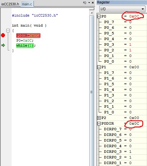
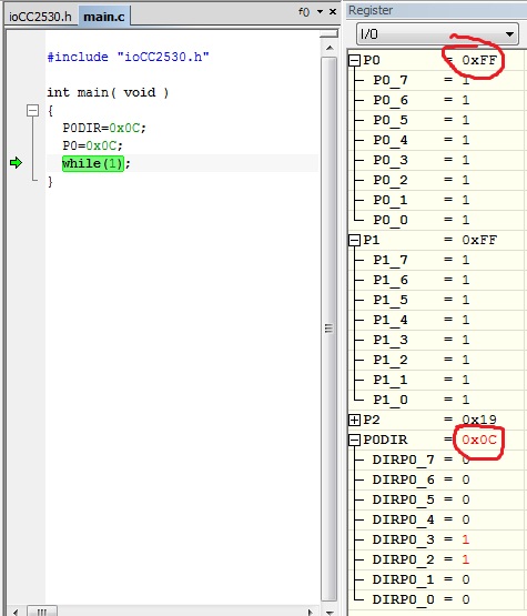
P0DIR=0x12;
P0|=0x12;
while(1);
}
Watching the I/O register window on debug mode I see that I can control the P0DIR register correctly (from reset 0x00 it becomes 0x12) but the P0 register stays stuck on 0xFF. Do you have any idea why this happens or how I can gain control over the pins. Thank you