This thread has been locked.

If you have a related question, please click the "Ask a related question" button in the top right corner. The newly created question will be automatically linked to this question.

CC1120 Transparent Serial Mode Troubles

Other Parts Discussed in Thread: CC1120

Hi,

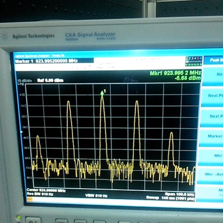
   When I use the CC1120 Transparent Serial Mode,I set  the CC1120 GPIO0  pin  is  explicitly  used  as  serial  data  input,and use the MCU to output a 40KHz digital signal to connect CC1120 GPIO0 ,but the Spectrum is so many harmonic wavelength,just like this picture:

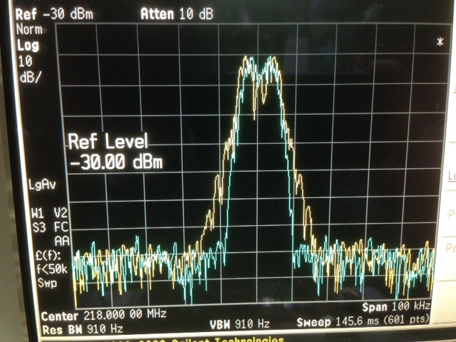
Compare with this one from using the  TrxEB PCB (MSP430 uP) and CC112xEM from SmartRF Studio 7 procreant which we wnat.

And this are the register settings:

static const registerSetting_t PreferredTxSettings[]=
{
  {CC112X_FREQ2,             0x71},    //730000
  {CC112X_FREQ1,             0xc0},
  {CC112X_FREQ0,             0x00},
  {CC112X_PA_CFG2,           0x30},//305664
  {CC112X_PA_CFG1,           0x56},     //WGH
  {CC112X_PA_CFG0,           0x64},    
  {CC112X_IOCFG3,            0x08},
  {CC112X_IOCFG2,            0x09},
  {CC112X_IOCFG1,            0xB0},
  {CC112X_IOCFG0,            0x30},     //48
  {CC112X_SYNC_CFG1,         0x0b},     //0x0b
  {CC112X_DEVIATION_M,       0x06},
  {CC112X_MODCFG_DEV_E,      0x1b},    //0x1b
  {CC112X_DCFILT_CFG,        0x1C},
  {CC112X_PREAMBLE_CFG1,     0x00},
  {CC112X_PREAMBLE_CFG0,     0x2A},
  {CC112X_IQIC,              0x46},
  {CC112X_CHAN_BW,           0x41},
  {CC112X_MDMCFG1,           0x06},
  {CC112X_MDMCFG0,           0x45},
  {CC112X_DRATE2,            0x94},    //0x84 by li
  {CC112X_DRATE1,            0x7a},    //7a
  {CC112X_DRATE0,            0xe1},//e1
  {CC112X_AGC_REF,           0x20},
  {CC112X_AGC_CS_THR,        0x19},
  {CC112X_AGC_CFG3,          0x91},
  {CC112X_AGC_CFG2,          0x20},
  {CC112X_AGC_CFG1,          0xA9},
  {CC112X_AGC_CFG0,          0xCF},
  {CC112X_FIFO_CFG,          0x00},
  {CC112X_SETTLING_CFG,      0x0B},
  {CC112X_FS_CFG,            0x12},
  {CC112X_PKT_CFG2,          0x07},    //0x07by li
  {CC112X_PKT_CFG1,          0x00},
  {CC112X_PKT_CFG0,          0x20},
  {CC112X_PA_CFG2,           0x30},//305664
  {CC112X_PA_CFG1,           0x56},     //WGH
  {CC112X_PA_CFG0,           0x64},
  {CC112X_IF_MIX_CFG,        0x00},
  {CC112X_FREQOFF_CFG,       0x00},
  {CC112X_TOC_CFG,           0x0A},
  {CC112X_FS_DIG1,           0x00},
  {CC112X_FS_DIG0,           0x5F},
  {CC112X_FS_CAL1,           0x40},
  {CC112X_FS_CAL0,           0x0E},
  {CC112X_FS_DIVTWO,         0x03},
  {CC112X_FS_DSM0,           0x33},
  {CC112X_FS_DVC0,           0x17},
  {CC112X_FS_PFD,            0x50},
  {CC112X_FS_PRE,            0x6E},
  {CC112X_FS_REG_DIV_CML,    0x14},
  {CC112X_FS_SPARE,          0xAC},
  {CC112X_FS_VCO0,           0xB4},
  {CC112X_XOSC5,             0x0E},
  {CC112X_XOSC1,             0x03},
  {CC112X_PARTNUMBER,        0x48},
  {CC112X_PARTVERSION,       0x21},
  {CC112X_SERIAL_STATUS,     0x08},
  {CC112X_RX_STATUS,         0x10},
  {CC112X_SETTLING_CFG,      0x0B},
};

Any suggests to me to solve the problem?

PS:

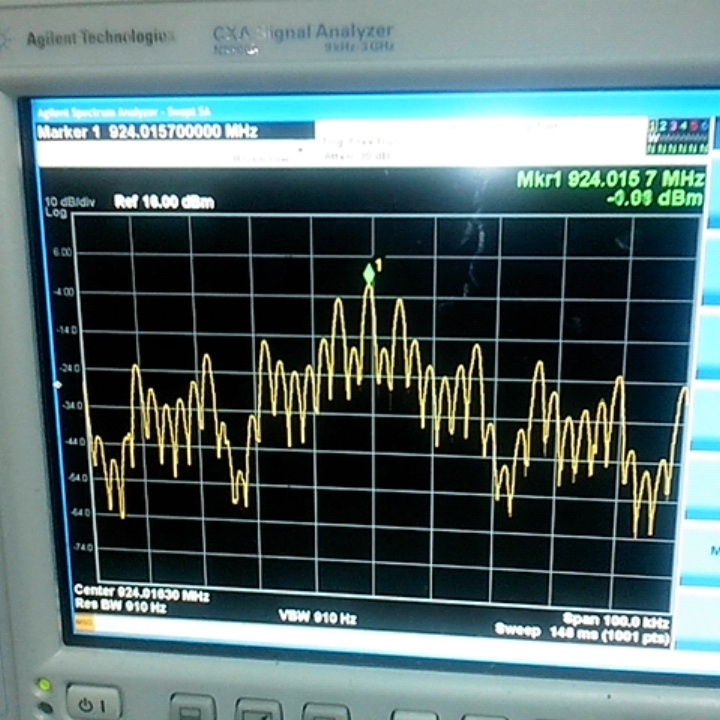
    When I use the  TrxEB PCB (MSP430 uP) and CC112xEM from SmartRF Studio 7,I didn't probe any digital signals

into the the CC1120 GPIO0  from MSP430 uP using the oscope.How does it produce the Spectrum.

 Best regards

Mickey Li

.

  • When you have low RBW you will observe the the line spectrum. When you transmit a 0-1 sequence you will see spikes at a distance given by the modulating frequency.

    To transmit random data set PKT_CFG2.PKT_FORMAT = 2. This option is included in SmartRF Studio: Continuous Tx -> Tick off "modulated" -> select data format "random mode".  Alternatively, use transparent mode and apply random data at the GPIO and not a 0-1 sequence as is the case if you use a square wave with fixed frequency as input source. 

  • Thanks Sverre,

                  When I use the  TrxEB PCB (MSP430 uP) and CC112xEM from SmartRF Studio 7 on CC1120 Transparent Serial Mode,I haven't probe any square wave put into  the CC1120 GPIO0  from MSP430 uP using the oscope.But in the spectrum I can see the modulated data,just like the follow picture .How does it work ?or how can configs registers?

     Thanks a lot!

  • The attached XML file can be imported into SmartRF Studio. Using these settings there will be no modulation unless you connect a signal to the GPIO acting as data input.

  • Thank you very much,Sverre.

    Though your help I have got 4-GFSK Spectrum,but in my application I want to use ASK/OOK mode,is it correct for use ?which registers need to change the value?

  • In SmartRF Studio there is a typical setting for OOK @4.8 kbps data rate. You can use this.

    For transparent serial mode select "Continuous RX" tab and "Data format" -> Transparent serial mode.

  • Thank you for answer.

    Yes,I have made the test.In my application want to use MCU's IO pin to control CC1120 GPIO0 pin as the modulated data.

    And in SmartRF Studio there is a typical setting for OOK @4.8 kbps data rate example, I never probed the TrxEB PCB (MSP430 uP) 's IO pin

    whitch connecting to CC1120 GPIO0 produce 4.8 kbps modulated data,where does it come from?

    How can I use extern MCU GPIO  as the modulated data?

  • See User Guide, section 7.7.2. http://www.ti.com/lit/swru295 

  • Although it's not my expect answer,thank you all the same.

  • Hi Sverre,

    Could you tell me how to import the XML file into SmartRf studio. We are testing a CC1120EM for operation in transparent serial mode.

    Thanks

  • In SmartRF Studio: File -> Open Cfg (or simply press F3)

  • Thanks Sverre,

    I get this error message

    7215.error_message.doc

  • The XML file was made in an older version of SmartRF Studio. 

    You can set the device up in Transparent mode as follows: Select "Continuous TX" tab and "Data format" -> Transparent serial mode.

    If you cannot get it to work, let me know the system parameters for your application (data rate, deviation RF frequency, ....) and I can generate a file for you.  

  • Hi Sverre,

    Thanks for clarifying the version issue - relief!! We currently have SmartRF studio 7 and 2off each CC1120EM with TrxEB.

    We would really appreciate any assistance from you to configure the CC1120EM.

    The design is to replace a FSK legacy module with customer data in and out that is serial TTL pre-manchestor coded and a Tx enable pin that is low for Tx and high for Rx.

    The old unit has a noise operated adjustable squelch "mute" pin. They also have a Rx tracking loop for frequency drift correction/tracking. The replacement hopefully using the CC1120 has to be backward compatible as the customer has many units in the field.

    The data rate is 2.4kbps; Deviation is 4Khz; Frequency is 868MHz band; Rx filter BW (-3dB) 14 Khz; Modulation 2GFSK.

    Look forward to hear from you.

    BP

  • "The data rate is 2.4kbps; Deviation is 4Khz; Frequency is 868MHz band; Rx filter BW (-3dB) 14 Khz; Modulation 2GFSK."

    The 99% occupied bandwidth is 9.5 kHz so allowing for frequency error between I would suggest 15 kHz RX filter BW and enabling FB2PLL (see User Guide for details). In short: setting FREQOFF_CFG = 0x30 the effective BW is 15 kHz +/-15 kHz/4, but the noise BW, which sets the sensitivity limit, is still 15 kHz.

    Attached is XML file for transparent serial RX. Not sure why you are not using the packet handling feature (automatic sync detect, data into RX FIFO,...), but this I something you should consider (although asynchronous serial mode works fine also)

    [View:http://e2e.ti.com/cfs-file.ashx/__key/communityserver-discussions-components-files/155/8053.2.4-kbps-4-kHz-dev-Transparent-RX.xml]

  • Thank you Sverre - I will try the settings.

  • Hi Sverre,

    Regarding your post of Sep 27 2014 08:55

    The Rx file settings works well for transparent serial mode with hardly any jitter - thank you!!

    To answer your question "Not sure why you are not using the packet handling feature" it is because we do not have a clock from the customer equipment - we just get TTL serial data in (for Tx) and give TTL serial data out (from Rx). I think we would need a clock to do it any other way - I maybe wrong!!

    What I noticed at powers below threshold and with no Rx signal is that there is a random stream of data pulses coming out. Is there some way of muting this data output and providing a signal to the customer equipment to ignore this Rx data stream?

    Will your file also be ok for transmitting in transparent serial mode?

    Regards BP

  • When the input signal is below the sensitivity limit or there is no signal the CC112x will demodulate noise and this is what you see on the data output pin. You can gate the reception with a carrier sense signal. This is explained in the User Guide.

    Based on the information you provided you can use the packet handling features when CC112x is the receiver assuming the packet transmits a preamble + sync word prior to the data payload.

    The settings will also work in TX

  • Thank you for the reply Sverre!

    Unfortunately our receive/transmit data has no preamble or sync word to use packet handling - it just has a couple of stop bits followed by a start bit.

    RX noise suppression:

    We loaded your file with SmartRF7 and made the following changes for carrier sense from the user guide:

    AGC_CS_THR = F2 (set threshold for -116dBm) Why is there a 102dB offset for this register?

    GPIO2_CFG = 11 (monitor carrier sense "CS")

    After clicking "start" on SmartRF7 we can see CS goes from high to low when the RF input is dropped below -116dBm but the data output stream is not stopped and the RSSI continues streaming on SmartRF7.

    If before clicking "start" we set the RF input lower than -116dBm then the data and RSSI stream are off. Is there some way of setting the CC1120EM from SmartRF7 so that data streaming stops and begins based on CS/RF input level without having to click "stop/start" from SmartRF7? What command is sent by SmartRF7 for "start"?

    If it cannot be done "automatically" by the CC1120 then we could gate the CS and data stream with some external cct.

    TX Transparent serial mode:

    We linked the CC1120EM to a legacy FM unit with attenuation and rf cables. With your file loaded we selected Continous Tx from SmartRF7 and compared the Tx datastream with the Rx datastream form the legacy unit. It works but there is about 3 times more jitter (35usec) than a link with two legacy units (10usec). Is there some way of reducing this jitter to be comparable to legacy units?

    Thank you for the support and look forward to your response.

    Regards BP

  • The -102 dB offset in the RSSI reading is explained in the CC1120 user guide, www.ti.com/lit/swru295, section 6.9. If you have a -102 dBm input signal the RSSI readout will be 0, hence you need to subtract -102 to convert the decimal reading into dBm.

    The carrier sense flag will be asserted in asynchronous serial mode if the received signal level is above the programmed threshold. The data output is not gated by CS. What you need to do is to use CS as an interrupt to the interfacing MCU and start looking for SOF after this flag is asserted. 

    Why use asynchronous mode on the TX side? If you use serial synchronous mode you get no jitter on the TX side. Data is then clocked into CC1120 on the rising edge of the data clock. In order to reduce jitter in asynchronous TX mode one thought is to increase the programmed data rate. 

  • Perfect Sverre, we understand the -102dB  => Thank you

    We will use the CS as an interupt. If by SOF you mean start of frame - unfortunately there is no preamble or sync word etc. The customer interface is just serial TTL data in and out and we have to be compatible with legacy FM units in the field. We want to use CS to mute the Rx data at low Rx power levels (noise). If we use CS to enable/disable an external switch when Rx is higher/lower than AGC_CS_THR will it be ok to achieve a mute function?

    We cannot use serial synchronous mode as the customer input is just serial TTL with no data clock or any other signal. We are forced to use Transparent serial mode. If we increase the programmed data rate (2.4kbps) to a higher value than the spectrum mask will be wider. Is there some other way you can think of reducing jitter?

    Thank you.

    BP

  • You can use CS to achieve a mute function.

    If you increase the programmed data rate the spectrum mask will not be affected. The data input in TX still has the same data rate and this (+ frequency deviation) is what defines the occupied bandwidth. If you increase the programmed data rate in asynchronous serial mode you simply increase the oversampling of the data input and this can potentially reduce the TX jitter.

  • Not sure if I am doing this correct Sverre to increase the programmed data rate.

    I loaded your file for transparent Rx serial mode and selected continous TX with transparent serial mode.

    With the original settings of 4KHz dev, 2.4kbps, 15KHz BW  I get the Tx mask in blue, nice and clean. The file I used from you is:

    <?xml version="1.0" encoding="ISO-8859-1"?>
    <!DOCTYPE configuration SYSTEM "C:/Program Files (x86)/Texas Instruments/SmartRF Tools/SmartRF Studio 7/config/xml/configdata.dtd"[]>
    <dcpanelconfiguration>
        <Devicename>CC1120</Devicename>
        <Description>Saved configuration data</Description>
        <registersettings>
            <Register>
                <Name>AGC_CFG0</Name>
                <Value>0xcf</Value>
            </Register>
            <Register>
                <Name>AGC_CFG1</Name>
                <Value>0x0a</Value>
            </Register>
            <Register>
                <Name>AGC_CS_THR</Name>
                <Value>0x19</Value>
            </Register>
            <Register>
                <Name>AGC_REF</Name>
                <Value>0x20</Value>
            </Register>
            <Register>
                <Name>CHAN_BW</Name>
                <Value>0x0d</Value>
            </Register>
            <Register>
                <Name>DCFILT_CFG</Name>
                <Value>0x1c</Value>
            </Register>
            <Register>
                <Name>FIFO_CFG</Name>
                <Value>0x00</Value>
            </Register>
            <Register>
                <Name>FREQ1</Name>
                <Value>0x80</Value>
            </Register>
            <Register>
                <Name>FREQ2</Name>
                <Value>0x6c</Value>
            </Register>
            <Register>
                <Name>FREQOFF_CFG</Name>
                <Value>0x30</Value>
            </Register>
            <Register>
                <Name>FS_CAL0</Name>
                <Value>0x0e</Value>
            </Register>
            <Register>
                <Name>FS_CAL1</Name>
                <Value>0x40</Value>
            </Register>
            <Register>
                <Name>FS_CFG</Name>
                <Value>0x12</Value>
            </Register>
            <Register>
                <Name>FS_DIG0</Name>
                <Value>0x5f</Value>
            </Register>
            <Register>
                <Name>FS_DIG1</Name>
                <Value>0x00</Value>
            </Register>
            <Register>
                <Name>FS_DIVTWO</Name>
                <Value>0x03</Value>
            </Register>
            <Register>
                <Name>FS_DSM0</Name>
                <Value>0x33</Value>
            </Register>
            <Register>
                <Name>FS_DVC0</Name>
                <Value>0x17</Value>
            </Register>
            <Register>
                <Name>FS_PFD</Name>
                <Value>0x50</Value>
            </Register>
            <Register>
                <Name>FS_PRE</Name>
                <Value>0x6e</Value>
            </Register>
            <Register>
                <Name>FS_REG_DIV_CML</Name>
                <Value>0x14</Value>
            </Register>
            <Register>
                <Name>FS_SPARE</Name>
                <Value>0xac</Value>
            </Register>
            <Register>
                <Name>FS_VCO0</Name>
                <Value>0xb4</Value>
            </Register>
            <Register>
                <Name>IF_MIX_CFG</Name>
                <Value>0x00</Value>
            </Register>
            <Register>
                <Name>IOCFG0</Name>
                <Value>0x09</Value>
            </Register>
            <Register>
                <Name>IOCFG1</Name>
                <Value>0xb0</Value>
            </Register>
            <Register>
                <Name>IOCFG2</Name>
                <Value>0x08</Value>
            </Register>
            <Register>
                <Name>IOCFG3</Name>
                <Value>0xb0</Value>
            </Register>
            <Register>
                <Name>IQIC</Name>
                <Value>0xc6</Value>
            </Register>
            <Register>
                <Name>MDMCFG0</Name>
                <Value>0x4a</Value>
            </Register>
            <Register>
                <Name>MDMCFG1</Name>
                <Value>0x06</Value>
            </Register>
            <Register>
                <Name>MODCFG_DEV_E</Name>
                <Value>0x0b</Value>
            </Register>
            <Register>
                <Name>PA_CFG0</Name>
                <Value>0x7e</Value>
            </Register>
            <Register>
                <Name>PKT_CFG0</Name>
                <Value>0x20</Value>
            </Register>
            <Register>
                <Name>PKT_CFG1</Name>
                <Value>0x00</Value>
            </Register>
            <Register>
                <Name>PKT_CFG2</Name>
                <Value>0x07</Value>
            </Register>
            <Register>
                <Name>PREAMBLE_CFG1</Name>
                <Value>0x00</Value>
            </Register>
            <Register>
                <Name>SERIAL_STATUS</Name>
                <Value>0x08</Value>
            </Register>
            <Register>
                <Name>SETTLING_CFG</Name>
                <Value>0x03</Value>
            </Register>
            <Register>
                <Name>SYMBOL_RATE2</Name>
                <Value>0x53</Value>
            </Register>
            <Register>
                <Name>SYNC0</Name>
                <Value>0xaa</Value>
            </Register>
            <Register>
                <Name>SYNC1</Name>
                <Value>0xaa</Value>
            </Register>
            <Register>
                <Name>SYNC2</Name>
                <Value>0xaa</Value>
            </Register>
            <Register>
                <Name>SYNC3</Name>
                <Value>0xaa</Value>
            </Register>
            <Register>
                <Name>SYNC_CFG1</Name>
                <Value>0x1f</Value>
            </Register>
            <Register>
                <Name>XOSC1</Name>
                <Value>0x03</Value>
            </Register>
            <Register>
                <Name>XOSC5</Name>
                <Value>0x0e</Value>
            </Register>
        </registersettings>
        <dcpanel>
            <Property role="44" name="m_chkRegView">2</Property>
            <Property role="44" name="m_chkRfParameters">2</Property>
            <Property role="37" name="m_tabUserMode">1</Property>
            <Property role="33" name="m_easyModeSettings">-1</Property>
            <Property role="33" name="m_typicalSettings">-1</Property>
            <Property role="37" name="m_testFuncPanel">1</Property>
        </dcpanel>
        <rfparameters>
            <Property role="46" name="m_cmbFrontends">0</Property>
            <Property role="44" name="m_chkHGMorBYP">2</Property>
            <Property role="46" name="m_cmbEmRevs">-1</Property>
            <Property role="46" name="Xtal frequency">32.000000</Property>
        </rfparameters>
        <conttx>
            <Property role="45" name="m_rbtModulated">1</Property>
            <Property role="45" name="m_rbtUnmodulated">0</Property>
            <Property role="46" name="m_cmbDataFormat">1</Property>
            <Property role="44" name="m_chkFreqSweep">0</Property>
            <Property role="44" name="m_chkChanSweep">0</Property>
        </conttx>
        <contrx>
            <Property role="46" name="m_cmbDataFormat">1</Property>
            <Property role="44" name="m_chkAutoScroll">2</Property>
        </contrx>
        <packettx>
            <Property role="42" name="m_edtPayloadSize">30</Property>
            <Property role="42" name="m_edtPacketCount">100</Property>
            <Property role="42" name="m_edtPacketCountEsy">100</Property>
            <Property role="42" name="m_edtRandomPacketData">13 0d 89 0a 1c db ae 32 20 9a 50 ee 40 78 36 fd 12 49 32 f6 9e 7d 49 dc ad 4f 14 f2 </Property>
            <Property role="42" name="m_edtPacketData"></Property>
            <Property role="42" name="m_edtAccessAddress"></Property>
            <Property role="42" name="m_edtDeviceAddress"></Property>
            <Property role="44" name="m_chkAddSeqNbr">2</Property>
            <Property role="44" name="m_chkInfinite">0</Property>
            <Property role="44" name="m_chkInfiniteEsy">0</Property>
            <Property role="45" name="m_rbtRandom">1</Property>
            <Property role="45" name="m_rbtText">0</Property>
            <Property role="45" name="m_rbtHex">0</Property>
            <Property role="44" name="m_chkAdvanced">0</Property>
        </packettx>
        <packetrx>
            <Property role="42" name="m_edtPacketCount">100</Property>
            <Property role="42" name="m_edtPacketCountEsy">100</Property>
            <Property role="42" name="m_edtAccessAddress"></Property>
            <Property role="44" name="m_chkInfinite">0</Property>
            <Property role="44" name="m_chkInfiniteEsy">0</Property>
            <Property role="46" name="m_cmbViewFormat">0</Property>
            <Property role="44" name="m_chkSeqNbrIncluded">2</Property>
            <Property role="42" name="m_edtDumpFile"></Property>
            <Property role="44" name="m_chkAdvanced">0</Property>
            <Property role="44" name="m_chk802154gMode">0</Property>
        </packetrx>
        <commandpanel>
            <Property role="44" name="m_chkInsertLength">0</Property>
            <Property role="42" name="m_edtTxFifo"></Property>
            <Property role="42" name="m_edtRxFifo"></Property>
            <Property role="46" name="m_cmbInstrInput">-1</Property>
        </commandpanel>
        <packetRxSniffMode>
            <Property role="42" name="m_edtPreambleLength">8</Property>
            <Property role="42" name="m_edtCarrierSenseThreshold">-90</Property>
            <Property role="45" name="m_rbtRssi">1</Property>
            <Property role="45" name="m_rbtPreamble">0</Property>
        </packetRxSniffMode>
    </dcpanelconfiguration>
    

    To increase data rate from SmartRF7 I changed symbol rate to 7ksps as the bit rate cannot be changed this gave me 7kbps bit rate.

    The Tx mask got wider as shown in the yellow plot

    The Jitter did reduce going from 2.4 to 7 ksps but the Tx mask gets worse.

    What am I doing wrong?

    Ps the frequency has been converted down to 218MHz from the original 868 MHz!!