This thread has been locked.

If you have a related question, please click the "Ask a related question" button in the top right corner. The newly created question will be automatically linked to this question.

CC2510 register config using SmartRF studio

Other Parts Discussed in Thread: CC2510

I am using the 'expert' mode in smartRF studio to configure the radio registers.

I want to transmit 1 byte with address and fixed pkt length. So pkt lenght = 2?
What should be the payload size and pkt count?

Is data whitening required?
What is 'Random' field? see attached.
What is Preamble count?
What should be the Sync word length?

  • - You have ticked the "Add seq number". This is for package testing to keep track of which packet you receive. Untick this box and the packet length will go down by one.

    - Yes, if you want to send 1 byte + adress = 2 byte payload with fixed packet length.

    - Whitening is not required but it is advisable that the data is fairly white (lot of '1' '0' transitions to ensure that the receiver works optimal) 

    - "Random field" is for packet testing, this will send x byte of random data. If you have a given payload you want to send, use the "text" or "hex" fields.

    - "Preamble count" is how many byte of preamble you send before the payload. This is required to settle the AGC on the receiver and to be able to lock on the bit stream.

  • Hello Hitesh, 

    The recommended setting is 4-byte preamble and 4-byte sync word, except for 500 kBaud data rate where the recommended preamble length is 8 bytes. I think your link will work with only 2 bytes sync word. But be aware of the preamble quality estimator threshold set in the PKTCTRL1 register. If this is to low you would be wise to at least use the 4 bytes payload to maybe reduce the chance of getting false detection's of  incorrect sync words and possibly noise.

    BR. Eirik

  • I don't understand the Random field still.
    I am using smartRF studio to configure RF registers and not doing any RF testing.

    The payload will be specific data(like number of button presses or temperature). This will change with each transmission. Should I change the random field to hex?
    what value should it be.

  • The "random", "text" and "hex" fields are included for easy testing with SmartRF Studio. As you see the register settings do not change if you go from "random" to "hex". When you use SmartRF Studio to generate register settings for your application the most important thing is to select if the packet length is fix or variable for the low left corner of the Studio window. In the first case you have to remember to set the correct length in the PKTLEN register.

  • Thanks.

    Do I import the register settings as .c file or .h file?

    I imported as .h file and added the file to project in IAR, but got an error saying not able to open ****.h file

    Should the .h file be in the inc folder.

  • As a .h file. See the examples in the CC2510 folders how to include the files.

  • Few more questions - 

    If I am sending just one packet at a time, what should the packet count be. 1?

    In smartRF studio Packet Tx/Rx tab, what does "seq number" mean? In which RF register is this stored.

    What does "address check, no broadcast" mean. I know addr check, but what does no broadcast mean.

  • Device address question - The device address register stores the address of the destination device?

    When you transmit a pkt with address check enabled, is the address entered manually or does the Radio insert the address.

    In SmartRF, what does the address field mean. Setting it will broadcast a pkt with entered address?

  • Hello Hitesh,

    Look at the "Packet Format" in the CC2510 data sheet. When enabled (like it is in the picture) the address will be entered automatically right after the length field byte if that is enabled. If not it will be right after the sync-word in the transmitted packet. When you make your own SW you will have to manually add the address byte in the packet payload.

    BR. Eirik

  • Hello Hitesh, 

    1) Yes packet count = 1

    2) Seq number is just a sequence number that SmartRFStudio adds to the payload. (Sequence number: a number that increments for each new transmitted packet).

    3) The broadcast means that you can check for additional address entries. For example if you want to listen to a user defined address 0xAA and also a broadcast address 0x00 (or both broadcast address 0x00 and 0xFF). This is explained in the Address Filtering section in the user guide.

    BR. Eirik

  • Eirik V. said:

    Hello Hitesh,

    Look at the "Packet Format" in the CC2510 data sheet. When enabled (like it is in the picture) the address will be entered automatically right after the length field byte if that is enabled. If not it will be right after the sync-word in the transmitted packet. When you make your own SW you will have to manually add the address byte in the packet payload.

    BR. Eirik

    Erik, 

    What do you mean by making your own SW?

    On my Tx board, there is no Device address. On the Rx board, the Address is 0x11 (Address register = 0x11). Once the Rx receives a pkt, it will check against this address(0x11). Right?

    When a pkt is sent from Tx, will it insert the address automatically?

  • Hello Hitesh,

    1. When you use your own SW you compile a code in IAR and download the firmware to run on the device (stand -alone).
    2. Yes, the device will check against the address 0x11. You must make sure that the transmitter use this address in the packets it is sending or else the receiver will not accept them.
    3. You must manually enter the address in the TX packet through the RFD register.
  • Eirik,

    Thanks for clarifying. 

    I am doing exactly as mentioned but I how do I know my code is working(transmitting). I tried to use CC2510mdk as receiver in smartRF studio, while another CC2510mdk is transmitting. But the received signal is flat.

    Here's my code. It transmits when a button is pressed -

    //**************RADIO CONFIG***************//

    GIE=1;// Global int

    RFTXRXIE=1; //RF INTERRUPT ENABLE 

    while(1) 

          {

                if (!P1_2) //button pressed(active low)

                      {

    bcount+=1;                 //button press counter
    RFST=0X03;              //Strobe TX
    RFD=rx1_addr;         // Pkt ADDRESS


    while(RFTXRXIF==1);              //wait for clear interrupt
    RFTXRXIF=0;                // reset and write data
    RFD=bcount;


    //repeat with same or dummy data, bcoz pktlen is 05
    while(RFTXRXIF==1);        //wait for clear interrupt
    RFTXRXIF=0;                    // reset and write data
    RFD=bcount;


    while(RFTXRXIF==1);        //wait for clear interrupt
    RFTXRXIF=0; // reset and write data
    RFD=bcount;


    while(RFTXRXIF==1);        //wait for clear interrupt
    RFTXRXIF=0;                    // reset and write data
    RFD=bcount; 

    P1_0 =1;
    delay();                  //LED stays ON for a while
    P1_0 =0;

    }
    //else enter low power mode with periodic wake up(1ms?)

                    }

  • Eirik,

    I found out I am not able to write to RF registers, specially the RFST and RFTXRXIF.

    I am writing RFST = 0x03; and making RFTXRSIF =0 ;

    When I debug, I don't see either of the registers change. RFST remains at 00. RFTXRXIF remains at 1.

    I am able to write to other registers like timer etc. But not the above 2 registers??????????????????

  • Well, finally I got the module to transmit something.

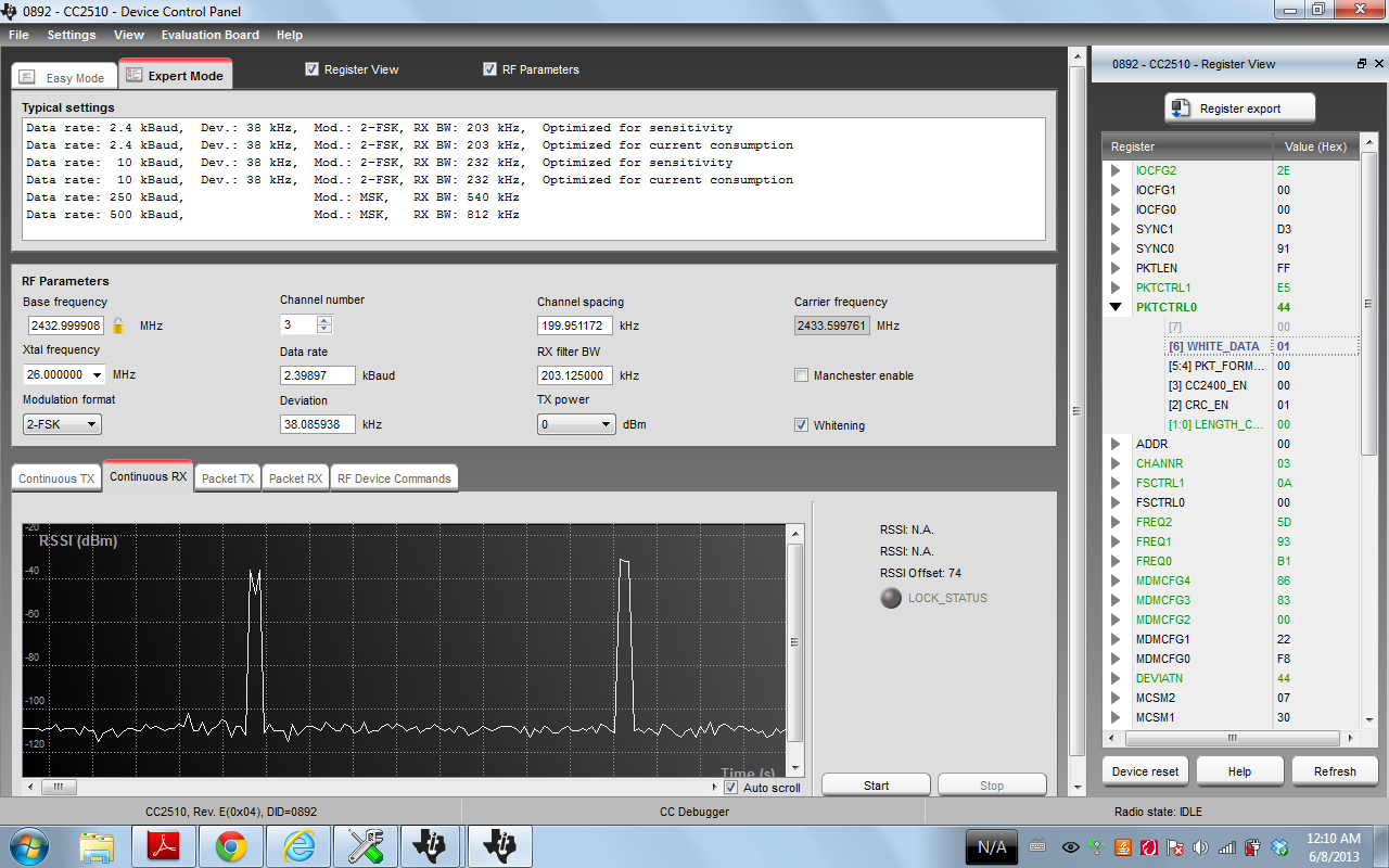
    In smartRF studio continuous mode, I can see the graph spike (see attached). I am transmitting just one packet with length=5. How do I extract the data?

    But when I try Packet Rx, I get nothing on the graph.