This thread has been locked.

If you have a related question, please click the "Ask a related question" button in the top right corner. The newly created question will be automatically linked to this question.

Arduino Sample Code

Other Parts Discussed in Thread: RF430CL330H, TRF7970A

Hi all, 

I am very interested in creating a dynamic nfc tag, so I bought the RF430 CL330H. As it supports I2C, I should be able to connect it to an Arduino and dynamically update the NDEF Message on it. Unfortunately, there is no demo code available. Does anyone have any code that could be shared (e.g. for Arduino, e.g. using Wire library -> http://arduino.cc/en/reference/wire)

I also have a few very basic questions - I assume - apologies in advance:

- is there a good NDEF lib that I could use to generate the byte arrays for the NDEF messages. All I am currently interested in is generating messages with single URL records in them, a method like getURLMessage(url) would be great

- VCORE - regulated core supply voltage - what does it mean? 3.3 V? VCC is clearly specified as 3.3 V

- I want to use I2C, so CS is connected to Ground - correct?

- do I have to connect E0/E1/E2 to low/high or is it optional to get the defaul addres (00101000 = 0x28 = dec 40) -   Wire.beginTransmission(40);

Thx!

Sven

  • Hi Sven,

    I am not aware of any Arduino code available.  We do have C code available as it sounds like you have already seen this. 

    • Have a look at the attached Excel formulas which can be used to generate the byte array for a URL message.  You should select "Basic Tag Application" for URL message.
    • Core voltage is 1.5V, but VCC is 3V - 3.6V.  The Vcore pin just needs a 0.47uF cap to ground for decoupling.
    • Correct, CS = GND selects I2C mode.
    • E0, E1, and E2 must be connected to some logic level to select the address.  If you want the address to be 0x28, you should ground these pins. 

    You can also reference the RF430CL330HTB board for an example of required connections.

    RF430CL330H_NDEF_Maker_v1_06_E.xlsm
  • Hi Eddie, thx a lot for the quick response.

    For the beginning, I will definitely first run the sample NDEF message that I copied out of the .h file - I assume that one is structurally correct and therefore should be a good example. But many thx for the Excel file, I will hopefully be able to use it soon.

    What I need to figure out is how to controle the NFC chip via I2C. Right now I do this in Wiring:

    #include <Wire.h>

    byte data[] = {/*sampel data here */ };

    void setup()
    {
    Serial.begin(9600);
    while(!Serial);

    Wire.begin();

    }

    void loop()
    {
    Wire.beginTransmission(40); // (0x28)
    int length = Wire.write(data, sizeof(data));
    Serial.println(length);
    Wire.endTransmission(); // stop transmitting
    }

    I am wondering if there is already the first issue. All I do rigth now is start the Arduino as I2C Master, begin the transmission to the default address and send the data. The data is a byte array of the sample ndef message provided in the .h file. On the Serial line, I get the message '48' which is the bytes transmitted. So far so good, but then when I place my Nexus 4 over the target board, nothing happens.

    I assume I forget all kind of stuff that I need to do do before transmittign the actual NDEF data. For example simply transmitting the bytes of the ndef message will likely not guarantee the message is written to the chips NDEF memory... I guess I have to address that somehow. How do I do that via I2C?

    When I look at the example code, it seems a very basic config woudl transmit the NDEF message and then turn on RF. My question: how do I transmit the NDEF data starting from address 0 vai I2C adn then turn on the RF? Would it be possible to get a small example of this?

    Thx

    Sven

  • I have now expanded my Arduino sketch code with what I believe is definitely necessary to do.

    I currently try to do this:

    1) disable the RF interface.

    Wire.beginTransmission(I2C_SLAVE); // (0x28)
    //Control register 0xFFFE
    Wire.write(0xFF);
    Wire.write(0xFE);
    //2 bytes of data
    Wire.write(0x00);
    Wire.write(0x00);
    Wire.endTransmission();

    -> this is addressing the I2C slave. Arduino has only 7bit addresses adn I assume the 8th bit, which needs to be 0, is set automatically as we are calling beginTransmission. I then continue to send the Address bytes -first FF and then FE - which I hope is adressing 0xFFEE. Next I send two bytes of data, in this case two times 0 as the RF should be turned off. 

    2) next I transmit the NDEF data. 

    Wire.beginTransmission(I2C_SLAVE); // (0x28)
    //Address the right register
    Wire.write(0x00);
    Wire.write(0x00);
    int length = Wire.write(data, sizeof(data));
    Serial.println(length);
    Wire.endTransmission(); // stop transmitting

    Again, I first start the communication in write mode using beginTransmission. Next, the register to address for the NDEF is starting at 0x0000 - so I transmit 0x00 and 0x00. next up is the NDEF data, which is contained in a byte array and the content is the text ndef record example. I can verify that data was transmitted as the length int is set to 48, so 48 bytes were transmitted.

    3) finally the RF interface needs to be turned on. 

    Wire.beginTransmission(I2C_SLAVE); // (0x28)
    //Control register 0xFFFE
    Wire.write(0xFF);
    Wire.write(0xFE);
    //2 bytes of data
    Wire.write(0x00);
    Wire.write(0x02);
    Wire.endTransmission(); // stop transmitting

    Here, I need to address the controle register again, whcih is 0xFFFE - so I transmit the high bits first, 0xFF and then 0xFE. To turn on the RF, bit 1 needs to be 1, which is 2 in DEC and 0x02 in HEX - all other bits are 0 so the first byte (15-8) is 0x00. 

    ---

    It still does not work... placing my phone (Nexus4) over the board does not trigger any activity in my phone. I connected my Android phone in debug mode to see if the NFC chip is being triggered by a RF field , but nothign at all. i assume the RF is not turned on.

    I think the problem that I have might be the addressing of the registers. Does the code provided above look logically correct?

    cu

    Sven

  • Sven,

    It looks like you have your data for the control register backwards.  See figure 4 in the datasheet.  Try switching to writing 0x02, 0x00.  Are you able to read the register back after you write it to ensure it was written?   


  • Sven,

    Also, I have attached logic analyzer shots of writing and reading the control register as well as the NDEF message.  Please note that I did not include the entire NDEF message write, but this should give you a clear picture of how it should look.  If you have a logic analyer as well, you can use this to compare.

    RF430CL330H_I2C_shots.zip
  • Eddie, 

    there is some progress. I am able to read the control register, and turn on the RF bit and write it back. The sequence right now is write the ndef, then access the control register, turn on RF. Unfortunately there is still an issue and it is a rather strange one. I assume I write the NDEF message incorrectly, as the URL that is sent from the chip to the mobile phone is ti.com/nfc - I assume this is a standard / default url in case something goes wrong. Can you confirm this?

    I'll be on vacation for 2 weeks now, but I will continue debugging thsi afterwards. Thx a lot for the help so far. I can - once back - also post the existing Arduino code that uses the I2C Wire Library. It is pretty straightforward once one understands the basics I guess. 

    Cheers

    Sven

  • Sven,

    You are correct.  The default message is ti.com/nfc.  It seems you must not be properly writing to the NDEF memory if this is still read when RF is enabled.  Do you have a logic analyzer that you could take some captures of the communication when writing your NDEF message?  This could help me in figuring out your issue. 

    Enjoy your vacation! 

  • Dear Eddie,

    I have a problem with  arduino. 

    I can read the default NDEF date with my nexus 7.

    but i have the register data backward, the data is wrong when first read. and the second it is correct.

    so i use two or more read command, like this:

    nfc.Write_Register(INT_ENABLE_REG, EOW_INT_ENABLE + EOR_INT_ENABLE);
    nfc.Read_Register(INT_ENABLE_REG);   // Error: data is wrong
    nfc.Read_Register(INT_ENABLE_REG);  // correct

    can you give me some advise?

    ----

    The xsl file is very useful. And

    0x00, 0x3B,     /* MLe (49 bytes); Maximum R-APDU data size */

     0x3B = 59. why not is 49 bytes?

    Thanks

    Ten

  • HI Ten,

    When you receive the wrong data, what data are you receiving?  What I2C clock frequency are you using?  If you have a logic analyzer, captures of the erroneous data could be helpful as well.

    The MLe is likely a typo.  This came from the example given in the NFC Forum type 4 tag specification.  For the RF430CL330H, this can actually be set to 0x00, 0xF0 for both MLe and MLc.  This will allow larger APDU sizes, which can provide higher data throughput.   

  • Dear Eddie,

    Thanks for your reply.  

    I have proved it. After send the Slave address, immediately send a stop, then read the data. it's ok.

    It is litter different with datasheet about I2C Read Access.

    I will see the logic with oscilloscope. but not now. A lot of work waiting to do.

     :)

    Ten

  • Hi Eddie, I am back from vacation and just spent time with the Arduino code again to use the NFC chip via I2C. I am still at the point where it activates the antenna but the NDEF url on the chip is the ti.com/nfc url. 

    Right now, when the arduino fires up, I write the NDEF and then I turn on the RF.

    writeNDEF(data);
    reset();

    Data is defined like this:

    byte data[] = {
    /*NDEF Tag Application */
    0xD2, 0x76, 0x00, 0x00, 0x85, 0x01, 0x01,

    0xE1, 0x03, /*Capability Container ID*/

    /* CC file start */
    0x00, 0x0F, /* CCLEN 15bytes fix*/
    0x20, /* Mapping version 2.0 */
    0x00, 0x3B, /* MLe (49 bytes); Maximum R-APDU data size */
    0x00, 0x34, /* MLc (52 bytes); Maximum C-APDU data size */
    0x04, /* Tag, File Control TLV (4 = NDEF file) */
    0x06, /* Length, File Control TLV (6 = 6 bytes of data for this tag) */
    0xE1, 0x04, /* Type4 Tag File Identifier */
    0x0B, 0xDF, /* Max NDEF size (3037 bytes of RF430CL330 useable memory) */
    0x00, /* NDEF file read access condition, read access without any security */
    0x00, /* NDEF file write access condition; write access without any security */
    /* CC file end */

    0xE1, 0x04, /* NDEF File ID */

    0x00, 0x0F, /* NDEF Length 15bytes */

    /* NDEF start */
    0xD1, /* NDEF Header MB=1, ME=1, CF=0, SR=1, IL=0, TNF=1 */

    0x01, /* Type Length 1 byte */

    0x0B, /* Payload length 11bytes */

    0x55, /* Type U (URI) */
    /* Payload start */

    0x01, /* URI Record Type : http://www. */
    /*Appliction Data : hybris.com */
    0x68, 0x79, 0x62, 0x72, 0x69, 0x73, 0x2E, 0x63,
    0x6F, 0x6D
    }; /* End of data */

    This byte array was created using the excel file you gave me (thx a lot again!).

    Then the actual code to send the data:

    void writeNDEF(byte data[])
    {
    int address = 0x0000;
    Wire.beginTransmission(I2C_SLAVE); // (0x28)
    Wire.write(address >> 8);
    Wire.write(address & 0xFF);

    for (int i = 0; i < sizeof(data); i++)
    {
    delay(10);
    Wire.write(data[i]);

    }
    //Wire.write(data2, sizeof(data2));
    Wire.endTransmission();
    }

    Can you maybe spot an issue there? I am not that strong in working with registers and all that stuff. Is the Address 0x0000 and how I send the byte values correct? Also, I simply iterate the byte array and write the bytes then of the ndef message. 

    One the writing has finished, I turn on the RF. In a recent example I first turned RF off, now I simply read the control register, turn RF on and write it back:

    void reset()
    {
    int address = 0xFFFE;

    delay(500);

    int control = readRegister(0xFFFE);
    control |= 2;
    Wire.beginTransmission(I2C_SLAVE); // (0x28)
    Wire.write(address >> 8);
    Wire.write(address & 0xFF);
    Wire.write(control & 0xFF);
    Wire.write(control >> 8);
    Wire.endTransmission();
    }

    Please let me know if you can spot an issue there....

    Cheers

    Sven

  • @Ten, I am wondering if you could also share your arduino code if you got some. It would be great to get a small, working sample sketch to update the nfc chip with a new NDEF url. Thx a lot!

  • Hey Sven,

    From a high level your code does seem to be good.  I'm going to assume that if you can read/write the registers that your low level I2C code is good as well.  

    Can you debug the code and step through it to see what it's doing?  I think you may have a code issue with the way in which you are passing "data[]" into the function.  

    Usually, to pass an array of bytes, you need to pass a pointer that points to the first byte of the array.  In this case, you may just be passing the first byte of the data[] array.  If this is the case, the sizeof() funcition is going probably going to return a 1, instead of the length of the actual array.  

    You might need to do something  For ex:

    byte data[3] = [1,2,3];
    
    _Function(&data[0]);
    
    void _Function(byte *data)
    {
       int temp = sizeof(*data);
    }

    Thanks,

    JD


  • Hi JD, Ed, 

    thx for pointing out the array issue. I refactored the code based on your input to rule out that I am not correctly addressing the array. I basically inlined the definition of the byte array and also used the Wire.write (array, length) method of the Wire library to send the array. 

    There are example out there that show exactly this and for others it seems to work (check here) http://forum.arduino.cc/index.php/topic,19581.0.html

    So, in total, it still activates the chip but gives me the same ti.com/nfc url when I use my phone.

    writeNDEF();
    reset();

    void reset()
    {
    int address = 0xFFFE;
    delay(500);

    int control = readRegister(0xFFFE);
    control |= 2;
    Wire.beginTransmission(I2C_SLAVE); // (0x28)
    Wire.write(address >> 8);
    Wire.write(address & 0xFF);
    Wire.write(control & 0xFF);
    Wire.write(control >> 8);
    Wire.endTransmission();
    }

    void writeNDEF()
    {
    byte data[] = {
    /*NDEF Tag Application */
    0xD2, 0x76, 0x00, 0x00, 0x85, 0x01, 0x01,

    0xE1, 0x03, /*Capability Container ID*/

    /* CC file start */
    0x00, 0x0F, /* CCLEN 15bytes fix*/
    0x20, /* Mapping version 2.0 */
    0x00, 0x3B, /* MLe (49 bytes); Maximum R-APDU data size */
    0x00, 0x34, /* MLc (52 bytes); Maximum C-APDU data size */
    0x04, /* Tag, File Control TLV (4 = NDEF file) */
    0x06, /* Length, File Control TLV (6 = 6 bytes of data for this tag) */
    0xE1, 0x04, /* Type4 Tag File Identifier */
    0x0B, 0xDF, /* Max NDEF size (3037 bytes of RF430CL330 useable memory) */
    0x00, /* NDEF file read access condition, read access without any security */
    0x00, /* NDEF file write access condition; write access without any security */
    /* CC file end */

    0xE1, 0x04, /* NDEF File ID */

    0x00, 0x0F, /* NDEF Length 15bytes */

    /* NDEF start */
    0xD1, /* NDEF Header MB=1, ME=1, CF=0, SR=1, IL=0, TNF=1 */

    0x01, /* Type Length 1 byte */

    0x0B, /* Payload length 11bytes */

    0x55, /* Type U (URI) */
    /* Payload start */

    0x01, /* URI Record Type : http://www. */
    /*Appliction Data : hybris.com */
    0x68, 0x79, 0x62, 0x72, 0x69, 0x73, 0x2E, 0x63,
    0x6F, 0x6D
    }; /* End of data */

    int address = 0x0000;
    Wire.beginTransmission(I2C_SLAVE); // (0x28)
    Wire.write(address >> 8);
    Wire.write(address & 0xFF);
    int written = Wire.write(data, sizeof(data));
    Serial.println(written, DEC);

    Wire.endTransmission();
    }

    I am sorry there is little progress. I am pretty sure this should all be correct, but maybe I am overseeing something. Could someone maybe share another example NDEF Message with me that I can use in the arduino code to rule out the issue with that?

  • Sven,

    Your issue is probably somewhere in the transmission of the NDEF message, not the NDEF message it self. You can generate more NDEF messages with the excel file Eddie send you for testing if you'd like.

    Do you know how fast your I2C clock is?  Do you know if the arduino support clock stretching?  I would probably try slowing your I2C clock down to like 120kb and see if that helps at all.

    Can you provide the source code for the wire.write() function so we can see exactly what it's doing?

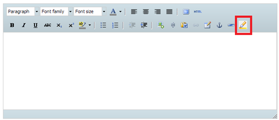
    Also, you can use the button highlighted below to insert your code and it will format it to make it a little more readable.  

    Thanks,

    JD 

  • Hi sven

    I just use this ic for my project. And it work well with me on arduino.  I share my code in https://github.com/awong1900/RF430CL330H_Shield .  

    Sorry to reply late. I use some time to tidy the code. 

    Hope useful for you.

    Thanks.

    Ten

  • Hi Ten,

    first let me tell you how extremely thankful I am. This is really great news for me. I already downloaded the code and am currently trying to run the write sample code. Right now it still shows me an empty tag when I place the nexus 4 over the antenna. But I think just some very very small issue with the correct wiring exists.

    I am using an Arduino Mega for this, have you been using Uno? It should not be an issue, I am just wondering if some pin numbers might need changing then. 

    You named the library ...Shield - and I also noticed a license file from Adafruit - is Adafruit selling a shield that I am not aware of? I am using the breakout board directly from TI. I had to solder a few pin headers to it and then use these to connect to the arduino mega.

    Here is the current wiring now:

    Breakoutboard - Arduino Mega

    GND - GND
    VCC - 3.3V

    SDA - 20 on Mega
    SCL - 21 on Mega

    CS - GND - means we use I2C

    It leaves the PIN 3 and 4 that you defined in the sketch yourself. I had never used these in my trials, maybe that's exactly my issue. I connected INT0 from to Pin 3 and RST from the breakout to Pin 4 on the Mega. Should that work? If that is correct, I still got an issue then as the tag read via the Nexus 4 is "blank".

    I feel I am very close to make this work, thx a lot for the help so far. It would be really great if I could get this up and running.

    Thx
    Sven 

  • Hi Ten, 

    I also quickly posted the breakout board that I use here https://plus.google.com/111621195174869691859/posts/9M9GnNiaTzG

    You can see the board connections, too. I am worried as there are two GND pins for example. I have connected one only as I hope that the board of course connects the two GNDs internally... So the pins connected are really VCC, GND, SDA/SCL CS and INT0 - nothing else. Does this look good to you?

    Again, thx!

    Sven

  • Hi Sven,

    For me, i use the arduino mega 2560.  And the connect is 

    E0,E1,E2,CS is GND,  SCK is not conncected.

    INT0 -- Pin3

    RST -- Pin4 ,   

    SDA -- Pin20,  10K up to 5V

    SCL -- Pin21,  10K up to 5V

    VCC -- 5V         Although the datasheet is 3V3, but 5V is also work . :) I will fix it and pull up power.

    GND -- GND 

    I was not use the official board. I use bread board welded myself.

    And the Adafruit is not sell the shield. but i borrow lots of codes about I2C from their project. So thx.

    Thanks

    Ten

  • Hi Sven, 

    I forgot a important thing. you must change the I2C's buffer in Wire library. 

    1.arduino-1.0.5\libraries\Wire\utility\twi.h

    #define TWI_BUFFER_LENGTH 255

    2.arduino-1.0.5\libraries\Wire\Wire.h

    #define BUFFER_LENGTH 255

    When i debugged the RF430, every time read the ndef data, just  32 bytes is right. It is hard to find.

    Then i changed the code , i forgot it. :)  

    I should remember earlier.

    Hope useful to you.

    Ten

  • Hi Sven and Ten,

    I read your discussion as I'm working on a similar project but I'm using Arduino Micro. I tried your sample code for reading and writing but it doesn't work as is because the external interrupt for the Arduino Micro are also assigned to TX, RX, SDA and SCL. I tried to comment out all the "Serial.*" commands and re-assigned the pins


    #define IRQ (1)
    #define RESET (5)


    My SDA, SCL, IRQ and Reset lines go to a bidirectional level shifter https://sjtbits.com/4-bit-level-converter/ then to the RF430CL30H TB. It didn't work or at least the TRF7970A EVM cannot detect it. I tried to connect them directly with the SDA and SCL pulled up to +5V and it still doesn't work. I got +5V reading in the VCC pin even if I supply +3.3V if I don't use the level shifter.

    I would appreciate any advice or suggestion.

    Thanks!

    Jason Sioquim

  • Hi Jason,

    I am sorry it took a while for me to reply, but I simply had no time and the email moved lower and lower in my email stack. 

    Good news: I am also using an Arduino Micro. I initially used the mega and then shrink-sized the project to micro. So I am very sure that it should work, as it works for me. 

    The trick is to use an "non-specified interrupt" - interrupt 4. 

    attachInterrupt(4, RF430_Interrupt, FALLING);

    The Micro is very similar to the Leonardo. After quite some trying I figured I check all interrupts of the leonardo, but with the micro. The interrupt 4 on the leonardo is PIN 7 - and the same PIN7 works for "interrupt 4" on the Micro. 

    http://arduino.cc/en/Reference/AttachInterrupt

    Have fun, let us all know if it works.

    One more comment - also to Ten: I think the RESET PIN is hardcoded in the lib, so no need to specify it. Ten could for example remove it from the arduino sketch. Have a look at the lib he wrote - the parameter internally is not used, but hardcoded. It did not bother me for my project, so I left that unchanged.

    Cheers

    Sven

  • Thanks Sven! I'll give this a try and will let you know if it works. I'm an absolute beginner in I2C and NFC but I would like to give this a shot as I needed this in a concept design I'm working on.

    Thanks again!

    Jason

  • Hi Sven,

    I changed all the attached interrupt to 4, as you've mentioned and I finally got the TRF7970A EVM to detect the RF430CL330H but I can't get anything from the serial monitor. I connected Pin7 on the Arduino Micro to INT0 and Pin5 to RESET. Below is how I set the IRQ and RESET.

    #define IRQ (4)
    #define RESET (5)

    Is this correct?

    I also changed the detatch interupt to 4 in the RF430_Interrupt function.

    void RF430_Interrupt()
    {
        into_fired = 1;
        detachInterrupt(4);//cancel interrupt
    }

    I may be missing a couple things? Let me know what you think.

    Thanks,

    Jason


  • Hi Sven,

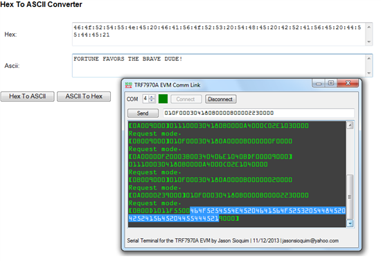
    I tried to read the data using the TRF7970A EVM and a serial terminal and it finally worked! Thanks for your help! I attached a snapshot of a serial terminal and the converted hex code with a test message.

    Cheers!

    Jason


  • Thanks for posting the library Ten. I am trying to write and read from control register but it is not reading the data i write. It returns 0. Do you know what is wrong? I am using arduino uno and irq is connected to pin 3 and reset is connected to pin 4. I have hooked exactly like the diagram shown here

    https://github.com/awong1900/RF430CL330H_Shield/blob/master/RF430CL330H_Shield.h

    except that since i am using uno i have connected the SDA and SCL to A4 and A5 in arduino. Thanks for the help! I will wait for the response.

    #include <Wire.h>

    #include <RF430CL330H_Shield.h>

    #define IRQ (3)
    #define RESET (4)

    RF430CL330H_Shield nfc(IRQ, RESET);

    void setup(void){

    Serial.begin(9600);

    nfc.begin();

    nfc.Write_Register(CONTROL_REG, 0x3131);

    delay(2000);

    Serial.println(nfc.Read_Register(CONTROL_REG));


    }

    void loop(void){

    while(true){


    }


    }

  • hey Ten,

    If you are still watching this thread i had a question for you. I noticed that in the library you implemented in the following function you are not using the IRQ parameter. Is that a mistake or was it commented out purposely? Please let me know. I am waiting for the reply. Thanks!

    /**
    ** @brief Instantiates a new RF430 class
    ** @param irq Location of the IRQ pin
    ** @param reset Location of the RSTPD_N pin
    **/
    RF430CL330H_Shield::RF430CL330H_Shield(uint8_t irq, uint8_t reset)
    {
    byte RxData[2] = {0,0};
    byte TxData[2] = {0,0};
    byte TxAddr[2] = {0,0};

    //_irq = irq;
    _reset = reset;

    //pinMode(_irq, INPUT); //other shield do not use this shield
    pinMode(_reset, OUTPUT);
    }

  • Hi Sanjay Giri,

    Long time no refresh this thread. I see with your email.

    In fact , the irq use the interrupt 1(pin3 on arduino). 

    Not need initialization.

    use irq with below:

    //enable irq
    attachInterrupt(1, RF430_Interrupt, FALLING);

    //disnable irq

    detachInterrupt(1);//cancel interrupt


    ---

    Ten 

  • oh..i think i saw attachInterrupt in the example code that was in the library folder. I will try it tomorrow and see if it works. Thanks!

  • Hi all,

    I am currently working on a university project which involves, passing data from an NFC phone to this TI device conected to an arduino µC, I have managed to transfer data to and from the device to the phone with use of Ten Wongs software though I am now trying to encode a raw binary data packets and send it through NFC, so far I have only been able to send URI messages from the device, would anyone please be able to help me with how to format the message so that it is picked up by the phone as raw date (integer array) rather than a URI message.

  • Maybe a proprietary encoded file would work better for you instead of NDEF.  In this type of message, you just specify PLEN(proprietary length field) and data.  You need to change the TLV blocks in the capability container to indicate a proprietary TLV.  The NFC Forum type 4 tag specfication outlines, in detail, how to format a proprietary file.  Let me know if this works out for you.

    http://nfc-forum.org/our-work/specifications-and-application-documents/    

  • I change the code for i2c read and write.  It will be use  less memory.

    So do not need change BUFFER_LENGTH and TWI_BUFFER_LENGTH.

    check out here:https://github.com/awong1900/RF430CL330H_Shield

  • Thanks for updating Ten.

    Appreciate it!

    -JD

  • Hi, NFC guys,

    I update my code again.  https://github.com/awong1900/RF430CL330H_Shield

    the point is easy to creat various NDEF format records,  such as URI, MIME, Text, External, Application and so on.

     //#record0 for URI
        records[0].createUri("https://github.com/awong1900/RF430CL330H_Shield");
    //#record4 for Application
        String packageName = "com.google.android.apps.maps";
        records[4].createApplicationRecord(packageName);

    --------------------------------------

    Below is advertisement. (If not allowed, please let me know)

    I want to share this ideas to everyone. So me and my friend made  a DNFC project on indiegogo.

    checkout:  http://igg.me/at/GOODNFCTAG/x/7649823

    At present, we provide the following open source resources to help get DNFC tag integrated into your system quickly:

    1.DNFC schematics

    2.DNFC Arduino sample code

    3.DNFC watering system sample source code and Android APP

    4. Android sample APP source code in WIFI password sharing system

    All files are completely open source, you can download it on our WIKI page.

    Ten