This thread has been locked.

If you have a related question, please click the "Ask a related question" button in the top right corner. The newly created question will be automatically linked to this question.

Problem with CC debugger

Other Parts Discussed in Thread: CC-DEBUGGER, CC2530, CC2591

Hi,

I have a problem with CC-debugger : 

When i try to program my CC2530 boards, (led of the CC-debugger is green) it shows a popup telling : "Warning : failed to erase flash" then it tells that the debugger initialization should have failed.

Then if i try again : 

"Tue Aug 27, 2013 12:20:38: Failed to initialize communication, debug session aborted."

Our board is a custom board, but we are using successfully CC debugger for 2 years. Our new board is the same as the previous one, excepting the DD, DC and nReset wires a little bit longer (but not more than 10cm).

I checked the signal : it is arriving to the CC2530.

Sometimes (very rare), programming seems to work, some boards have even started (so they are working properly, it is only an evolution of our work.

Is there a capacitance or something like this to add to the debugging circuit to improve it stability ?

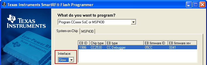
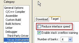
CC debugger has been updated to the latest version, and we are using an IAR 8.20.1 version with a dongle.

Thanks and best regards,

Valentin

  • Hi,

    People sometimes experience issues with flashing devices if the bottom side ground pad of the device isn't properly grounded/soldered. This may be what is causing the flash programming instability.

    Br,
    TIABO 

  • Hello Tiabo,

    I have one query regarding the reset of cc debugger. I have used the sw_redetect software that you have shared and facing some issues with it.

    Issue is posted @ http://e2e.ti.com/support/low_power_rf/f/155/p/231170/998170.aspx

    Can you please help me with the resolution of the same?

    Regards,

    Shriharsh

  • Thanks for your reply,

    I will check this point with our board manufacturer very soon. It is possible, because we have found 2 boards out of 6 programming and debugging correctly all the time.

    Best regards,

    Valentin

  • Hi,

    We have checked with our PCB assembler, but everything is ok concerning the soldering of the ground pad. We have even replaced the CC2530 with another one (of the same serie) but we have the same problem.

    The problem seems to be at the first programmation phase, We have 2 out of 6 PCB where CC2530 flashing is ok and the 4 other ones tell us "failed to erase flash".

    I checked the connections of DC / DD and Reset but there is no problem on these...

    If you have other ideas, you're really welcome, we are blocked for 4 days now on this strange problem.

  • Hi,

    Have you tried lowering the interface speed?

    Br,
    TIABO 

  • Hi,

    Is it possible to change the speed from IAR, we program all our devices from there.

    However, i compared the waveforms using a workinbg board and the waveforms using the non working board during programming, and there is no difference.

    We have also tested the reference voltage : on all boards we get 1.27V on RBias and 1.88V on DCOUPL.

    We have also a STRONG indication : we tested both 32MHz and 32.768kHz quartz.

    On pin 23 and 32, we have a good signal on working boards and  no signal on non-working boards. We have tested this for all our boards (6) and it is totally reproductible. Test has been done after connecting the CC-Debugger and pushing the reset button without programming.

    What can cause the quartz not to work ? We think that soldering process was good (it is done industrially with an trusted refusion oven.

    I hope that you can help us, best regards,

    Valentin

  • Hi,

    You can reduce the the interface speed in IAR under Project > Options > General Options > Debugger > Texas Instruments > Target.

    I will have to get back to you with regards to the oscillator symptom.

    Br,
    TIABO 

  • Hi,

    We have tested reducing the interface speed, but it is not working better...

    We think that all is correct on our board, so we will do a next test. We are going to unsolder a CC2530 that is known to be working on another board, and resolder it on our new board to see if the CC2530 that causes troubles can be incriminated.

    Best regards,

    Valentin

  • Hi Valentin,

    Any luck with resoldering/swapping devices? 

  • Hi,

    We tried to swap the device with a working one on another board, but it doesn't work ! Programming is sometimes successful but really slower than a normal programming under IAR.

    We really don't know what happens, we think there is a criticity on the placement of the capacitors around the chip. All our capacitors were on the bottom layer link with a via to the top layer of the CC2530. 

    I think a will do a new design following exactly the CC2591 reference design.

    Do you have some other ideas ?

    Best regards,

    Valentin

  • Hi Valentin,

    Could you please attach an image of your setup.

  • Hi Igor,

    Sorry for the delay, here is the schematics and the layout top and bottom of the CC2530 + CC2591 design.

    We still have the problem, we really don't see what happens, and we are considering a new design.

    If you have some ideas, they are really welcome.

    Best regards,

    Valentin

  • Hi Valentin,

    Sorry for the late reply, I was abroad.

    From your schematic, I can't see how exactly the debugger connects to CC2530 device.

    Are there any vias between the large pad (CC2530 #41 pad) to a solid ground. I can see

    the ground pad connected to a solid ground through pins 1-4, is that all?

  • Hi Igor,

    Here is a view where you can see the 4 vias connecting the ground pad to the GND internal plane and the bottom ground plane.

    For the programmation pins, they are connected to the other side of the board with a 7cm net for each signal. PGD, PGC and nReset are not perfectly parallel, but their length are about the same.

    Any ideas ?

    Best regards,

    Valentin

  • Hey,

    Could you replace the Cap and a Resistor on nReset net with 1nF and 2.2KOhm?

  • Hi,

    We tried it but unsuccessfully. 

    Valentin

  • Hi Valentin,

    Somehow I've managed to miss this post of yours:

    Val 83 said:
    We have also a STRONG indication : we tested both 32MHz and 32.768kHz quartz.

    On pin 23 and 32, we have a good signal on working boards and  no signal on non-working boards. We have tested this for all our boards (6) and it is totally reproductible. Test has been done after connecting the CC-Debugger and pushing the reset button without programming.

    What can cause the quartz not to work ? We think that soldering process was good (it is done industrially with an trusted refusion oven.

    Are the values of C105, C106, C107 and C108 on working boards are the same as on non-working?

    Anyhow, try to replace C105 and C106 with 18pF caps (or better with 27pF).

  • Thankx for your reply,

    Actually it was a wrong indication from me. CC2530 starts its oscillators after botting and of course after programming. By default, it is using the internal RC oscillator. That's why the boards impossible to program have thier quartz not working and the good ones have their quartz operationnal.

    But we still have our problem. We tried to manufacture another board making some modifications such as capacitor placement and a full ground plane under the CC2530, especially on the bottom side. We also tried to respect a similar path for all the 3 programmation nets.

    We will know if it is correcting the problem next week...

  • It's kindda obvious, but I have to ask the ground of CC debugger connected to the ground

    of CC2530, and you have VCC feedback from your board connected to the CC debugger?

  • Surely, it is connected via the ground internal plane and the bottom plane.

    We have also VCC feedback connected to our board. We use the CC debugger to power the board during programmation.

  • Well, I have two more ideas:

    • cold soldering, means, it looks like all pins are soldered, but there's
      no galvanic connection 
      between a pad/s to a pin/s of CC2530.
      Happened to me once, totally 
      drove me crazy for almost a week.
    • Have you tried to work with another CC Debugger, or smartRF05EB?

    Besides that I ran out of ideas

  • We tried also using other CC-Debugger, we have 6 or 7 units, but it is still the same behaviour.

    We also tried to solve a potential cold soldering problem : we have unsoldered the "not programmable" CC2530 and resoldered another one "known to be working in another board", with an IR rework tool. It is the wame behaviour also.

    I agree with you, i don't have anymore ideas, it really is the first time a see such a problem, without seeing any solution.

    Anyway, if you have another idea...

  • Have you tried to power the boards with an external power source (i.e. not the CC Debugger)?

    TIABO