This thread has been locked.

If you have a related question, please click the "Ask a related question" button in the top right corner. The newly created question will be automatically linked to this question.

CC1120 sometimes sends with wrong central freq

Other Parts Discussed in Thread: CC1120

Hello,

I read many articles but at the end I didn't find any solution.

In my hw I've a host controller and a CC1120 connected using SPI at 8 MHz.

My code has the following 3 steps:

1) init the CC1120

2) put the module in continous TX and after 3 secs put the module in IDLE

3) reset the CC1120.

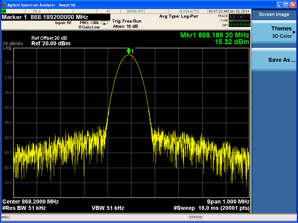
These 3 steps are in a loop, and in the 90% of cases I saw the carrier at the expected frequency (868.200 MHz).

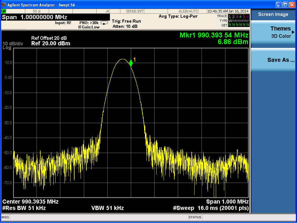
In the 10% of cases, the carrier is shifted forward of 100/150 MHz.

I read and implemented the manual calibration in the init, and everytime the loop start, I repeat the manual calibration.

My init function performs the following steps:

move Up the RESET_N pin and it stays for 20ms

move Down the RESET_N pin and it stays for 20ms

move Up the RESET_N pin and it stays for 20ms

Wait until the module status is not Chip_Not_Ready

Send all my register configurations using SPI

Strobe(Idle)

Read PARTVERSION and if it is 0x21 I'll perform a manual calibration but just after enabling in the CC1120_SETTLING_CFG register the 'manual calibration'

Strobe(NOP) in order to read the status of CC1120.

Any suggestions?

Thanks in advance

Alex

  • - Which frequency do you send on when sending on the wrong frequency.

    - Could you post the complete code? From reading your description it sounds like you do it correctly but if that was the case you would not end up sending on the wrong frequency.

  • TER said:

    - Which frequency do you send on when sending on the wrong frequency.

    The Freq is about 990 MHz

    TER said:

    - Could you post the complete code? From reading your description it sounds like you do it correctly but if that was the case you would not end up sending on the wrong frequency.

    --------

    Initialization

    --------

    For the calculation of Fc we use the formula provided by the datasheet:

    void CC1120_CalculateFrequency(unsigned long Frequency, unsigned char* TabFreq)
    {
    /*Reglage de la frequence de la porteuse*/
    unsigned long Calculated_value;
    unsigned long intermed1 = (unsigned long)((0.262144*((Frequency)/32)));
    unsigned long inter2 = ((127*65536)/262144);// Freqoff = 0x7F

    Calculated_value = (unsigned long)(intermed1-inter2);

    /*configuration de la frequence*/
    TabFreq[0]= (unsigned char) (Calculated_value & 0x000000FF);
    TabFreq[1]= (unsigned char) ((Calculated_value & 0x0000FF00)>> 8u);
    TabFreq[2]= (unsigned char) ((Calculated_value & 0x00FF0000)>> 16u);
    }

    unsigned char CC1120_Radio_Init (unsigned long Frequency)
    {
      unsigned char i;
      static unsigned char cTemp;
      unsigned char tuc_CC1120_Frequency[3];
      
      if(!HardInitDone)
      {
        //First start TCXO
        CC1120_Switch_On_Tcxo();
        
        //RESET pin set to 0 to init CC1120
        SFX_Set_Digital_Output(RADIO_RESET_PIN, 1);
        SFX_Wait_MicroSecond(2000);
        SFX_Set_Digital_Output(RADIO_RESET_PIN, 0);
        SFX_Wait_MicroSecond(2000);
        SFX_Set_Digital_Output(RADIO_RESET_PIN, 1);
    
        //SFX_Set_Digital_Output(LED_RADIO_PIN, 0);
        
        if (SPI_Init() < 0)  //SPI port initialisation on µC
          return -1;
        
        //Wait end of Power On Reset of radio chip	
        do
        {
          SFX_Wait_MicroSecond(100);
          SPI_Strobe(CC1120_SNOP);
        }
        while(CC1120_Status & CC1120_CHIP_NOT_RDY_bm);         
        HardInitDone = true;
      }


    //  SPI_Strobe(CC1120_SIDLE);
    
    
      // -- Send the common part config into CC1120 registers --
      for(i=0; i<23; i++)
        SPI_Exchange(SPI_WRITE, HighPerfMode[i].addr, HighPerfMode[i].data, &cTemp);
    
      
      /*Calcul la valeur des registres en fonction de la frequence demandée*/
      CC1120_CalculateFrequency(Frequency, tuc_CC1120_Frequency);
    
      /*Config*/
      CC1120_SetCenterFrequency(tuc_CC1120_Frequency);
    
      SPI_Strobe(CC1120_SIDLE);
      // -- Check that the chip is in the corect state
      SPI_Exchange(SPI_READ, CC1120_PARTVERSION, SPI_NOP, &cTemp);
      if(cTemp == 0x21)
        CC1120_manualCalibration();
    
      
      SPI_Strobe(CC1120_SNOP);
      if((CC1120_Status & CC1120_STATE_bm) == CC1120_STATE_IDLE) //IDLE state
        return 0;
      else
        return -1;
    }
    void CC1120_manualCalibration(void)
    { 
      unsigned char original_fs_cal2; 
      unsigned char calResults_for_vcdac_start_high[3]; 
      unsigned char calResults_for_vcdac_start_mid[3]; 
      unsigned char marcstate; 
      unsigned char writeByte; 
      unsigned char cTemp;
    
      /* Put the module in manual calibration if needed*/
      SPI_Exchange(SPI_READ, CC1120_SETTLING_CFG, SPI_NOP, &cTemp);
      
      if(cTemp & 0x18)
      {
        writeByte = (cTemp & (~(0x18)));
        SPI_Exchange(SPI_WRITE, CC1120_SETTLING_CFG, writeByte, &cTemp);
      }
    
      // 1) Set VCO cap-array to 0 (FS_VCO2 = 0x00) 
      SPI_Exchange(SPI_WRITE, CC1120_FS_VCO2, 0x00, &cTemp);
         
      // 2) Start with high VCDAC (original VCDAC_START + 2):  
      SPI_Exchange(SPI_READ, CC1120_FS_CAL2, SPI_NOP, &original_fs_cal2);
      writeByte = original_fs_cal2 + VCDAC_START_OFFSET;
      SPI_Exchange(SPI_WRITE, CC1120_FS_CAL2, writeByte, &cTemp);
         
      // 3) Calibrate and wait for calibration to be done (radio back in IDLE state) 
      SPI_Strobe(CC1120_SCAL);
      do { 
        SPI_Exchange(SPI_READ, CC1120_MARCSTATE, SPI_NOP, &marcstate);
      } while (marcstate != 0x41); 
        
      // 4) Read FS_VCO2, FS_VCO4 and FS_CHP register obtained with high VCDAC_START value 
      SPI_Exchange(SPI_READ, CC1120_FS_VCO2, SPI_NOP, &calResults_for_vcdac_start_high[FS_VCO2_INDEX]);
      SPI_Exchange(SPI_READ, CC1120_FS_VCO4, SPI_NOP, &calResults_for_vcdac_start_high[FS_VCO4_INDEX]);
      SPI_Exchange(SPI_READ, CC1120_FS_CHP, SPI_NOP, &calResults_for_vcdac_start_high[FS_CHP_INDEX]);
           
      // 5) Set VCO cap-array to 0 (FS_VCO2 = 0x00) 
      SPI_Exchange(SPI_WRITE, CC1120_FS_VCO2, 0x00, &cTemp);
             
      // 6) Continue with mid VCDAC (original VCDAC_START):  
      SPI_Exchange(SPI_WRITE, CC1120_FS_CAL2, original_fs_cal2, &cTemp);
       
      // 7) Calibrate and wait for calibration to be done (radio back in IDLE state)
      SPI_Strobe(CC1120_SCAL);
      do { 
        SPI_Exchange(SPI_READ, CC1120_MARCSTATE, SPI_NOP, &marcstate);
      } while (marcstate != 0x41); 
         
      // 8) Read FS_VCO2, FS_VCO4 and FS_CHP register obtained with mid VCDAC_START value 
      SPI_Exchange(SPI_READ, CC1120_FS_VCO2, SPI_NOP, &calResults_for_vcdac_start_mid[FS_VCO2_INDEX]);
      SPI_Exchange(SPI_READ, CC1120_FS_VCO4, SPI_NOP, &calResults_for_vcdac_start_mid[FS_VCO4_INDEX]);
      SPI_Exchange(SPI_READ, CC1120_FS_CHP, SPI_NOP, &calResults_for_vcdac_start_mid[FS_CHP_INDEX]);
          
      // 9) Write back highest FS_VCO2 and corresponding FS_VCO and FS_CHP result 
      if (calResults_for_vcdac_start_high[FS_VCO2_INDEX] > calResults_for_vcdac_start_mid[FS_VCO2_INDEX]) { 
        SPI_Exchange(SPI_WRITE, CC1120_FS_VCO2, calResults_for_vcdac_start_high[FS_VCO2_INDEX], &cTemp);
        SPI_Exchange(SPI_WRITE, CC1120_FS_VCO4, calResults_for_vcdac_start_high[FS_VCO4_INDEX], &cTemp);
        SPI_Exchange(SPI_WRITE, CC1120_FS_CHP, calResults_for_vcdac_start_high[FS_CHP_INDEX], &cTemp);
      } 
      else { 
        SPI_Exchange(SPI_WRITE, CC1120_FS_VCO2, calResults_for_vcdac_start_mid[FS_VCO2_INDEX], &cTemp);
        SPI_Exchange(SPI_WRITE, CC1120_FS_VCO4, calResults_for_vcdac_start_mid[FS_VCO4_INDEX], &cTemp);
        SPI_Exchange(SPI_WRITE, CC1120_FS_CHP, calResults_for_vcdac_start_mid[FS_CHP_INDEX], &cTemp);
      } 
    }

    Start Tx
    void CC1120_StartRf(void)
    {
        SPI_Strobe(CC1120_STX);
        SFX_Wait_MicroSecond(20);  
    }

    StopTx

    void CC1120_StopRf(void)
    {
        SPI_Strobe(CC1120_SIDLE);
    }

    Thanks in advance
  • Just an idea:

    can the problem be connected to the SPI speed?

    I'm using a SCLK of 8 MHz, but during manual calibration i need to read some extended register (TCXO 32 MHZ) and reading the datasheet i found an upper limit of 6 MHz for extended memeory reading operation.

    is this the 'answer'???

  • It could be. Try to set the SPI speed to 4 MHz (or something with some margin to max).

    Also: Try to run the manual calibration just once at the start (if you are not already doing so) If this fixed the issue it is the manual calibration.

    Also: Try to set the FREQ word as a value taken from SmartRF Studio and not calculate it.