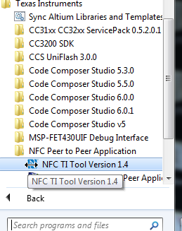
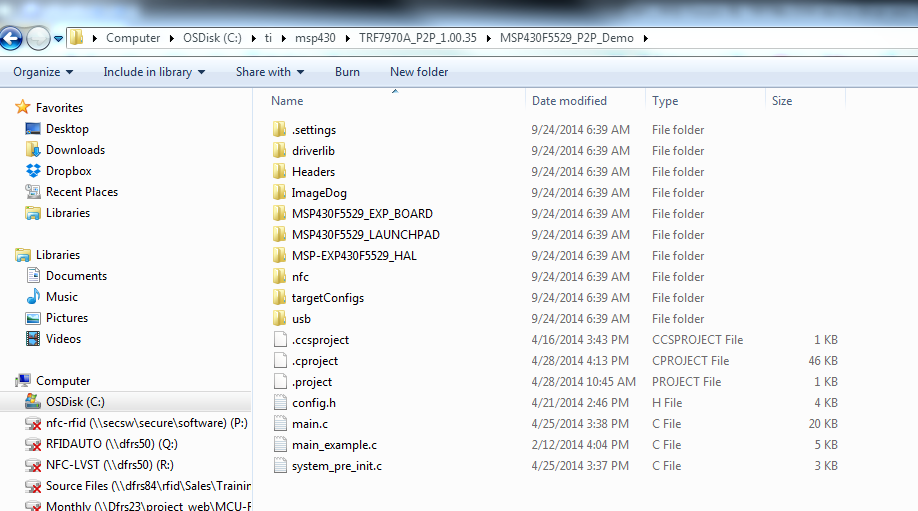
Please send a direct link to install the drivers and GUI for TRF796X evaluation board
This thread has been locked.
If you have a related question, please click the "Ask a related question" button in the top right corner. The newly created question will be automatically linked to this question.
Hi,
Please let me know what is the reading range of TRF796x at half power and full power? It is not mentioned in the datasheet.
Pragnya -
read range is not limited only by the power out of the transmitter. other main variables are: size of the reader antenna, Q of the reader antenna, Q of the tag antenna, size of the tag antenna, resulting coupling factor between the two and the activation field strength required by the tag. So, while it seems a simple question to ask and be answered...its not quite as simple as you think without the other data points to reference. if its not too much trouble, please let me know what size antenna and which tag silicon and size you are looking at using, and then i can repeat the simple test you see done in the attached at 1/2 power out, but with something closer to what you want to do - so as to give you a good idea of where you will come out.
3771.TRF7960_Read_Range_Slides.pdf
also, if you have a look at the TRF7960ATB user manual, in section 14 (page 19), you will see some more data about reading range. ==> http://www.ti.com/lit/ug/slou297/slou297.pdf
Thank you Mr. Josh, the ppt that you had attached gave me a fair amount of idea about the read range. I am not able to give you the details of the antenna as our electronics team is yet to decide on the design details.But the info you gave is very useful thanks again.
I had another question about the TRF7960 EVM board. I want to operate the TRF7960 in direct mode 1.
I am giving the following commands:
1) bit 6 in the ISO control register
2) Write register
3) read register
Now I want to know how to get a proof that the tag is in direct mode 1. I have used the get version command in the "test" tab to see if the get the same response from the tag, as I get when I put the tag in other ISO protocol modes. actually I get the same response in all the cases
"11:44:44.906 --> 0108000304FE0000
11:44:45.062 <-- 0108000304FE0000
Firmware Version 3.2.EXP.NOBB".
But is this test good enough to prove that the tag is in direct mode 1 or is there any other command to prove the same.
Please help.
Regards,
Pragnya
for DM1, you first write the ISO control register (lets say with a 0x42, for ISO15693 or a 0x48, for ISO14443A, etc.), then write the Chip Status Control register with 0x61 and leave the SS line low.
then use I/O_5 and I/O_6 are your clock and data lines...is there a particular reason you want to use DM1?
That's a very good question...I wanted to use my own software protocol so that I didn't have to change the software in my current system, when I chalked out the details, I figured out that I dont have make a lot of changes as I had assumed, I am going to use IS015693 now, thanks a lot for asking that right question,it actually saved a lot of my time :-)
Hello Mr. Josh,
In the system that we are planning to design we want the transponder( we will be designing our own transponder) to send the data to the reader continuously whithout receiving even a single initial command. Is it possible to achieve this using any of the 4 protocols that the TRF79XX supports or should I use the directmode where I can design my own protocol.
Also, please clear my understanding about the directmode 0 : As i understand it,this mode, puts the data I am sending on the carrier (amplitude modulates the carrier according to the data bytes), is this right?
Also please explain Direct Mode1 from the reader and transponder point of view.( what is sent from the reader and what is received at the transpoder and viceversa)
do you mean the transponder you are designing will be emitting its own field and messages?
(just trying to clarify what you are intending to do here.)
if so, at what frequency?
as normally, the reader will be the "master" send out a command and then expect a response from the transponder, on a sub carrier frequency. The reader could be placed into a listen mode, but please explain more...
now then, if the device you are designing is emitting @ 13.56MHz, then you are leaning more towards what peer to peer communication is, and its defined already (going on many years now, in ECMA340 and later ISO18092, now very specified by NFC Forum) - so you may want to leverage that, if that is your intent...then you would be better suited to using the TRF7970A for both sides, where you can in fact do active and passive P2P with the device and not re-invent the wheel.
Hi Mr. Josh,
We already have a transponder like circuit which transmits the data continuosly at the frequency 13.56 Mhz and we will be reusing the same.
I had another question : Can I talk to the MSP430 in the EVM board through hyperterminal/ access port instaed of the GUI provided by TI for the EVM board. If yes, then what baud rate should I set up in the settings tab of the hyperterminal/access port?
Thanks you Mr. Josh.
Actually, I want to read the version number from the reader using hyperterminal.
I have configured the hyperterminal as 115200bps 8N1 and the ISO cmd i am sending is
01 0A 00 03 04 18 01 FE 00 00
but I do not receive any response from the reader.
But if I send the following EVM command, to get the version number,
from the TI GUI, I get the proper response
01 08 00 03 04 FE 00 00
Please let me know where I am going wrong
thanks
I got it its responding, I had to change the format in which i was entering the command
Aslo please answer the following question for me:
Instead of a Tag, we are using another board say Board A which reads data from a sensor and puts it on uart lines.Now on the EVM board, we have removed the component C13 and we have connected the Uart Tx line from the Board A to RX1_AM (pin 8) of the TRF796x.Is it possible to read the data comming out of the Board A on the TI GUI? Also please let us known the data frame( start of frame etc) that we have to send from Borad A to enable it to be read by the TI GUI , assuming our data is 0xABCD.
To add more clarification to the above statement, we are actually building a customized tag. Please let us know what should be the bit rate of the bits comming out of Board A. Can I use the Uart Tx line of Board A in this case or I have to use a I/O pin and toggle the pin according to the ISO protocol with the expected bit rate?
Also, please let us know your phone number so that we can talk to you directly.
Thank you
Hello,
Please let me know if I can establish peer to peer communication between either of the setups I have
1. TRF7960 EVM board and TRF7970 EVM board.
OR
2. TRF7970 EVM board and TRF7970A target board.
In the second set up, I have SPI communication between TRF7970 target board and my board. My board contains Atmega88 controller. I can program the Atmega controller to send commands to TRF7970.
If peer- to peer communication is not possible in both the above mentioned set ups, please let me know what is the right setup and let me know the details of how to achieve.
This helps me to build proof of concept for my up comming project, urgent help is required on this. Please help me.
Thanks and Regards,
Pragnya
Please send a link to the latest NFC P2P firmware...In the link
http://www.ti.com/lit/zip/sloa192 only GUI installer is available..
Thanks Josh,
I had 1 more question
I checked the following configuration on the eval boards using the code given by you i.e.TRF7970AEVM P2P May 14 3704.TRF7970AEVM P2P May 14.zip
But the other way round was not working: