This thread has been locked.

If you have a related question, please click the "Ask a related question" button in the top right corner. The newly created question will be automatically linked to this question.

cc1101 RXBYTES always zero

Other Parts Discussed in Thread: MSP430G2553, CC1101

Hi guys!

   I have been set GDO0 to 0x06 (SYNC Word detected) and connected it to my uC (MSP430G2553). I wait to GDO0 interrupt my uC and read RXBYTES before read RXBUFFER. When an interrupt occurred, i read RXBYTES and its always zero (0x00).

   I try to read RXBuffer but it contains trash... can anybody help me to solve this problem?

I configured the CC1101 register like this:

static const registerSetting_t tagsettings[]= 
{
  {CC1101_IOCFG0,        0x06},
  {CC1101_FIFOTHR,       0x41},
  {CC1101_SYNC1,         0xC9},
  {CC1101_SYNC0,         0x9E},
  {CC1101_PKTLEN,        0x9E},
  {CC1101_PKTCTRL1,      0x0C},
  {CC1101_PKTCTRL0,      0x01},
  {CC1101_ADDR,          0x09},
  {CC1101_FSCTRL1,       0x06},
  {CC1101_FSCTRL0,       0x00},
  {CC1101_FREQ2,         0x21},
  {CC1101_FREQ1,         0x63},
  {CC1101_FREQ0,         0x02},
  {CC1101_MDMCFG4,       0xCA},
  {CC1101_MDMCFG3,       0x83},
  {CC1101_MDMCFG2,       0x13},
  {CC1101_MDMCFG1,       0xA2},
  {CC1101_MDMCFG0,       0xF8},
  {CC1101_DEVIATN,       0x34},
  //{CC1101_MCSM2,         0x10},
  {CC1101_MCSM1,         0x30},
  {CC1101_MCSM0,         0x38},
  {CC1101_FOCCFG,        0x16},
  {CC1101_BSCFG,         0x6C},
  {CC1101_WORCTRL,       0xFB},
  {CC1101_FSCAL3,        0xEF},
  {CC1101_FSCAL2,        0x0C},
  {CC1101_FSCAL1,        0x3B},
  {CC1101_FSCAL0,        0x1F},
  {CC1101_TEST2,         0x88},
  {CC1101_TEST1,         0x31},
  {CC1101_TEST0,         0x09},
};

  • Hi

    You have enabled CRC auto flush (PKTCTRL1 = 0x0C). This will flush the RXFIFO if you have a bit fault in the packet. Try to disable the CRC auto flush and see if you can read from the FIFO then.

  • Hi Martin,

       i change PKTCTRL=0x04, to disable CRC auto flush, but i can't read FIFO and RXBYTES is still zero... this is my code:

     // wait for packet received interrupt 
        if(packetSemaphore == ISR_ACTION_REQUIRED)
        {
            cc1101SpiReadReg(CC1101_RXBYTES,&rxBytesVerify,1);


            do
            {
              rxBytes = rxBytesVerify;
              cc1101SpiReadReg(CC1101_RXBYTES,&rxBytesVerify,1);
                      }
            while(rxBytes != rxBytesVerify);
            
            cc1101SpiReadRxFifo(rxBuffer,(rxBytes));
            
            // check CRC ok (CRC_OK: bit7 in second status byte)
            if(rxBuffer[rxBytes-1] & 0x80)
            {
              // toggle led
               halLedToggle(LED1);
              // update packet counter
              packetCounter++;
            }
          
          // reset packet semaphore
         packetSemaphore = ISR_IDLE;
         
              
          // set radio back in RX
          trxSpiCmdStrobe(CC1101_SRX);
          
          
        }

    I await any suggestion....

    Best regards,

  • How have you set up the interrupt? Are you interrupting on rising or falling edge of the GDO0 signal?

  • Hi Martin,

       thanks for your soon response. I have set up the interrupt... in the code that i showed, always enter when i transmitt.

    In my code,"packetSemaphore = ISR_ACTION_REQUIRED", when GDO0 interruption occurred. But in code line 15, rxBytes is always zero, so i dont read anything in rxbuffer...  i forced to read some bytes but read trash... that i don't know is why interrupt GDO0 when transmitt but the rxbuffer its empty.

    if I read RSSI register, i see a correct value (-40 dbm aprox).

    Best regards,

  • Sorry but my latest post might have been a bit vague. Let my be more precise. It's not clear form the post how you set up the ISR. Be sure that your MCU is set up to trigger on the falling edge of the GDO signal, and verify with a scope or logic analyzer that the GDO signal on the receiver side acts like excepted. I.E. the signal asserts when a sync word is received, stays high through the entire payload and goes low at the end of the packet. I can be helpful to monitor the same signal on the transmitter to verify that the GDO signal is the same on both the transmitter and receiver. 

  • I have exactly same problem with you. and cannot find out the reason.

    1 out of 2 of my device have this problem

  • Hi Martin,

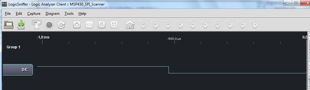
        attached  GDO0 signal from my logic analyzer (only works at 4mhz and small buffer).

        however, i'm sure that GDO0 interrupt uC because i'm used the SmartRF04 EB program modified in this post:

    http://e2e.ti.com/support/low_power_rf/f/155/t/301463.aspx

     P2SEL &= ~0x40; // P2SEL bit 6 (GDO0) set to one as default. Set to zero (I/O)
      // connect ISR function to GPIO0, interrupt on falling edge
      trxIsrConnect(GPIO_0, FALLING_EDGE, &radioRxTxISR);
      
      // enable interrupt from GPIO_0
      trxEnableInt(GPIO_0);

    I understand that CC1101 read de sync words, because if i change the sync word in configuratión, GDO0 don't interrupt uC and i think that there are a reason that dont write fifo_rx, but i don't know why...

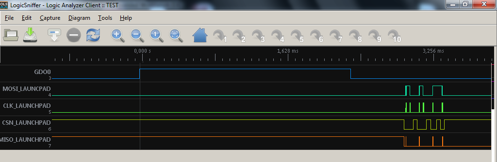
  • Finally, i can show you these signal with a new logic analyzer that i purchased:

    Now you can see that GDO signal goes on an I read TXBYTES and obtain ZERO than result of this operation...

  • Hi

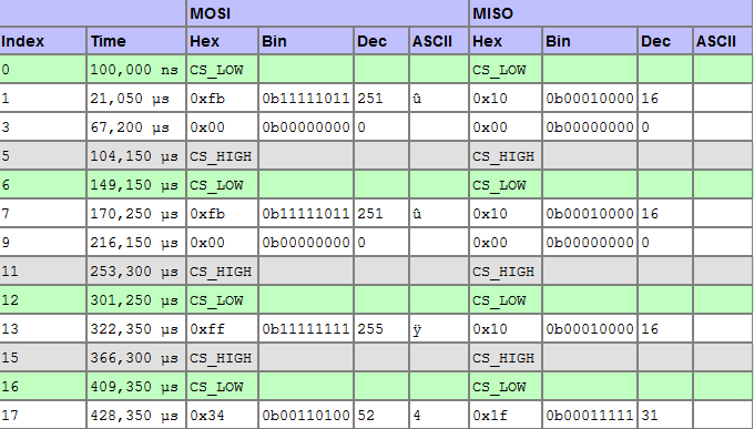
    I noticed from you SPI list that the returned status byte indicates that the radio is still in RX. This usually indicates that the radio has discarded the packet due to filtering, either address, packet length or CRC fault.

    The register settings you posted in the start of the post is a bit ambiguous. For instance; you have set an address for the device but are not using address filtering. You had also enabled the CRC_AUTOFLUSH without having CRC enabled (I know you have changed this later on).

    My recommendation is to do a test with default register settings exported from SmartRF Studio without any changes. Then send a standard packet that is within the FIFO limit, for example:

    0x05 0x01 0x02 0x03 0x04 0x05

    look at the GDO signal and check that the signals stays high throughout the entire payload and verify that the radio has gone to IDLE after reception. Then read RXBYTES and the RXFIFO content.

  • Hi Martin,

       finally i have solved this problem with a timer tha do this actions:

    // set radio in iddle
    trxSpiCmdStrobe(CC1101_SIDLE | RADIO_READ_ACCESS);
    //calibrate
    trxSpiCmdStrobe(CC1101_SCAL | RADIO_READ_ACCESS);
    //back in RX
    trxSpiCmdStrobe(CC1101_SRX);

    because i have seen that the rx fifo overflow when receive a data... and i dont know why...

    Best regards!