Hello,
I have a custom PCB with a CC2540 and I am trying to modify SimpleBLEPeripheral. I have two buttons on the board at P1.2 and P1.3. The SimpleBLEPeripheral firmware with the Keyfob build has two buttons, one will switch advertising on and off. The Keyfob buttons are connected to P0.0 and P0.1. I'm unsure how to change the code to set the buttons up on P1.2 and P1.3 instead?
  P0SEL = 0; // Configure Port 0 as GPIO
  P1SEL = 0; // Configure Port 1 as GPIO
  P2SEL = 0; // Configure Port 2 as GPIO

  P0DIR = 0xFC; // Port 0 pins P0.0 and P0.1 as input (buttons), all others (P0.2-P0.7) as output
  P1DIR = 0xFF; // All port 1 pins (P1.0-P1.7) as output
  P2DIR = 0x1F; // All port 1 pins (P2.0-P2.4) as output

  P0 = 0x03; // All pins on port 0 to low except for P0.0 and P0.1 (buttons)
  P1 = 0;   // All pins on port 1 to low
  P2 = 0;   // All pins on port 2 to low
I'm guessing I need to change this code but where do the 0xFC, 0xFF etc. come from? How can I work out what 0xXX I need to have P1.2 and P1.3 set as input? I have spent hours reading the developers guides and searching the forums but I'm lost.
I am new to firmware coding (as you can probably tell!) so thanks for helping out a newbie!
Cheers
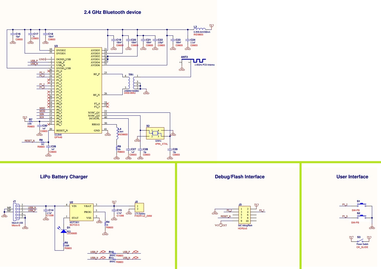
Edit with the pic of the schematic