Hai,
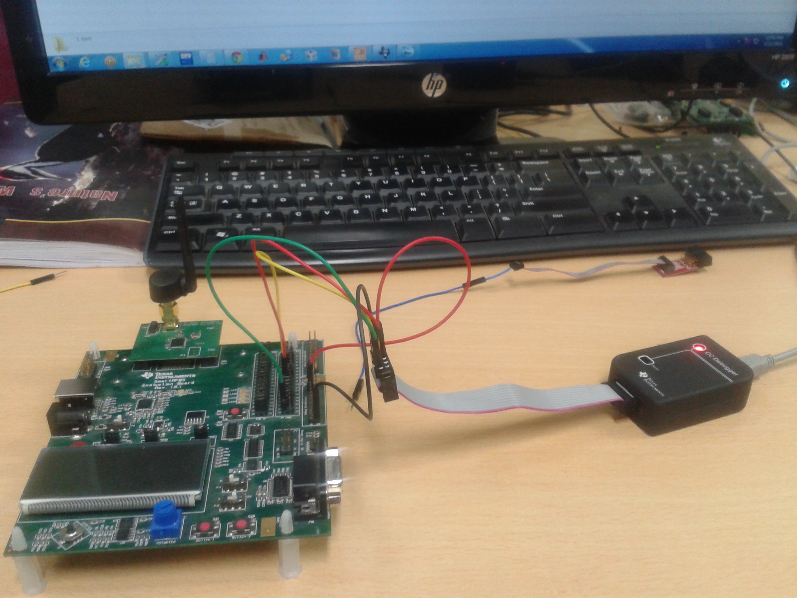
is it possible to dump the code into CC2530EM using SmartRF with CCDbugger(Not with USB cable)..??
if yes, please provide some documents..!!
Hai,
is it possible to dump the code into CC2530EM using SmartRF with CCDbugger(Not with USB cable)..??
if yes, please provide some documents..!!