This thread has been locked.

If you have a related question, please click the "Ask a related question" button in the top right corner. The newly created question will be automatically linked to this question.

how to get the real working RSSI in smartRF studio 7

Other Parts Discussed in Thread: CC2591, CC2530, Z-STACK, CC2590, CC2592, CSD

hi ,

     there are two device , one is ZED which was always in searching network

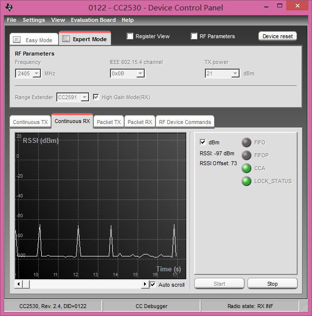
     the other one was connected the CC debugger to the PC ,and open the smartRF studio 7  Continueous RX window, as below


     there are so many question about this process

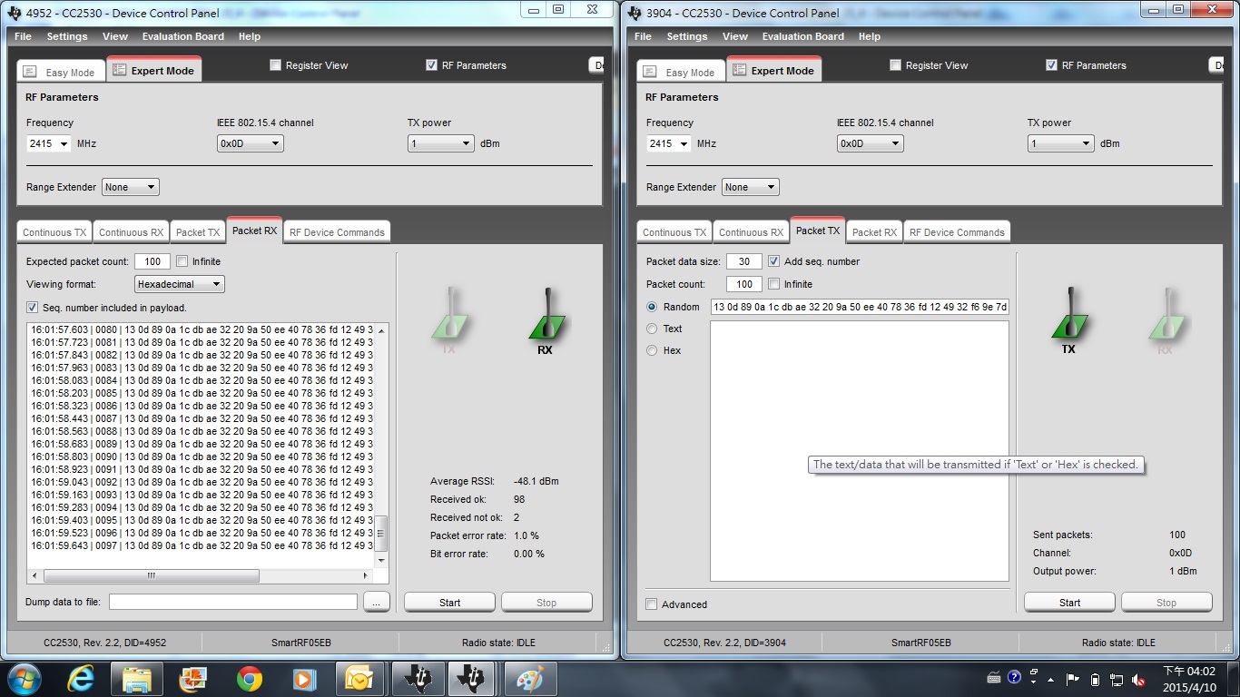
    1. nomatter  what value of  Txpower  i had set , there is nothing different happen in the Continueous RX window

    2. when i turn off the ZED ,stop searching, and there are not any more devices, The Continueous RX window also could catch something 

    3.what is the highest value in  Continueous RX window ,is that  real searching network signal?

    4. how could i catch  the RSSI value in real product working moment

BR!

  • If you are interested in the RSSI for a received signal you should read the RSSI from the RSSI register for a received packet.

    The peeks you see in the SmartRF Studio window is the packets your sender is sending but the time resolution is low hence it's not possible to get the accurate RSSI when receiving a packet.

    Why do you want to find the RSSI?
  • because our product which used CC2530+CC2591 was so bad .

    i want to test when the device send out a remote message to ZCD ,

    how much power was lost

  • You can use one CC2530+CC2591 which applies Packet TX on SmartRF studio 7 and another CC2530+CC2591 which applies Packet RX. In this way, you can see RSSI and PER.

  • The seven: " our product which used CC2530+CC2591 was so bad ": Do you get lower range than expected? Or what is your definition of bad?

    Do you use a board from TI or have you made your own CC2530+CC2591 board?
  • Hi TER

             what do i mean is that the LQI was not so good . and i was use my own board.

            maybe  i have got some point of it

           1.  when i change the default channel  from  0x0B to 0x18,  It seems that the LQI was better。

           2.  i have not change anything about the TXpower at first time , but when i add  a code “ macRadioSetTxPower(21)"   in the APP.c  init function

                the RSSI was improve 10dbm


          so i  think that the channel 0x0B was not so good , and zstack default TXpower was not the max one。

         do  you think so?

    BR

  • If you use Z-Stack for CC2530+CC2591, the default TX power is not set to 21dbm.
  • so what is the default value of TXPOWER in this mode
  • The default is 19 dbm.
  • but i am always didn't know  what is the meaning of the item in the TXpower setting function。

    as coding like “macRadioSetTxPower(21)"  , what is the meaning of  "21"   

    is that the real value of dBm? if it is , how could we set a minus one ?  is  that ok coding like this ” macRadioSetTxPower(-11)"  “

    or is that was only the  index of  the TXPOWER table ?

    but I saw the TXPOWER table as like below , ”21“ could not fit for anything~~~~ 

  • anymore ,why only open the RX _HGM  just while  ”paLnaChip == PA_LNA_SE2431L“  ???

    is that RX_HGM mode is  better than RX_LGM mode


    MAC_INTERNAL_API void macRadioTurnOnPower(void)
    {
      /* Enable RF error trap */
      MAC_MCU_RFERR_ENABLE_INTERRUPT();

    #if defined MAC_RUNTIME_CC2591 || defined MAC_RUNTIME_CC2590 || \
        defined MAC_RUNTIME_SE2431L || defined MAC_RUNTIME_CC2592
      /* table ID is referenced only when runtime configuration is enabled */
      if (macRadioDefsRefTableId & 0xf0)
    #endif /* defined MAC_RUNTIME_CC2591 || defined MAC_RUNTIME_CC2590 */

    #if defined MAC_RUNTIME_CC2591 || defined MAC_RUNTIME_CC2590 || \
        defined MAC_RUNTIME_SE2431L || defined MAC_RUNTIME_CC2592 || \
        defined HAL_PA_LNA || defined HAL_PA_LNA_CC2590 || \
        defined HAL_PA_LNA_SE2431L || defined HAL_PA_LNA_CC2592
      { /* either if compound statement or non-conditional compound statement */
       
        /* (Re-)Configure PA and LNA control signals to RF frontend chips.
        * Note that The register values are not retained during sleep.
        */
       
        if (paLnaChip == PA_LNA_SE2431L)
        {
          /* CPS or P0_7 maps closely to the HGM line */
          HAL_PA_LNA_RX_HGM();
     
          /* EN or CSD line is controlled via software so setting it high here to start the SE2431L frontend */
          HAL_PA_LNA_RX_CSD_HIGH();
         
          /* CTX or P1_1 maps closely to PAEN */
          RFC_OBS_CTRL0 = RFC_OBS_CTRL_PA_PD_INV;
          OBSSEL1       = OBSSEL_OBS_CTRL0;
        }
        else if(paLnaChip == PA_LNA_CC2592)
        {
          /* P1_1 -> PAEN */
          RFC_OBS_CTRL0 = RFC_OBS_CTRL_PA_PD_INV;
          OBSSEL1       = OBSSEL_OBS_CTRL0;
         
          /* P1_0 -> EN (LNA control) */
          RFC_OBS_CTRL1 = RFC_OBS_CTRL_LNAMIX_PD_INV;
          OBSSEL0       = OBSSEL_OBS_CTRL1;
        } 
        else
        {  
          /* P1_1 -> PAEN */
          RFC_OBS_CTRL0 = RFC_OBS_CTRL_PA_PD_INV;
          OBSSEL1       = OBSSEL_OBS_CTRL0;
         
         
          RFC_OBS_CTRL1 = RFC_OBS_CTRL_LNAMIX_PD_INV;
         
    #ifdef RFC_OBSSEL
          /* Use user-defined pin as EN (LNA control) */
          RFC_OBSSEL    = OBSSEL_OBS_CTRL1;
    #else
          /* P1_4 -> EN (LNA control) */
          OBSSEL4       = OBSSEL_OBS_CTRL1;
    #endif
        }
       

  • 21 in maxSetTxPower is dbm. You can only use dbm as parameter. If you intend to set min TX power which is 10, you have to use 10 as input parameter.
  • 1. When you use CC259X, RX_HGM mode is set in HAL_BOARD_RF_FRONTEND_SETUP of HAL_BOARD_INIT().

    2. Yes, RX_HGM mode is  better than RX_LGM mode.