This thread has been locked.

If you have a related question, please click the "Ask a related question" button in the top right corner. The newly created question will be automatically linked to this question.

Sending \ recieving signals to Port 0

Other Parts Discussed in Thread: CC2431, CC2430, CC2510, SIMPLICITI, CC2530

Hi I am hooking a compass to the CC2431 blind node. The compass is already hooked to PO.5, P0.6 and P0.7. I am basically trying to send data to the compass and need to know how to send siganls to these pins. What function is there to send signals to these pins? I looked in the iocc2431.c but I could not find it. So please let me know which functions I need to use to send siganls to these pins. I am kind of new to this area and would really appreciate some help as I want to write a driver for the compass hooked on to the SOC_BB's Port 0. Thanks.

  • Hello

    First anything below after double slashes (//) are comments and not code. I'm assuming you are using IAR, and that you have the include files etc. I have not included the code to set up the clocks etc. It is just enough code to answer your question, I can add more detail as you need it.

    Reviewing the CC2430 data sheet (page 83 of 211) will help understand the following. Using the ports as I/O is easy and only requires a few commands to get started. First you have to set the P0SEL register to 0 for the pin you want to use if you want to use it as a GPIO (general purpose I/O) port and not a peripheral such as SPI or something else. Next you have to set P0DIR bit for the port pin you are setting  to 1 if you want it to be an output. That is all.   Now if you write  P0_7 = 1;   Port 0 bit 7 will become high. If you write P0_6 = 0; Port 0 pin 6 will be low.


    int main(void)
    {

    // PORT 0      
    // Anything after double slashes are comments and not code

    P0SEL &= ~BIT7    // Set P0 bit 7   to 0   for GPIO  (see note at the bottom)
    P0SEL &= ~BIT6    // Set P0 bit 6   to 0   for GPIO
    P0SEL &= ~BIT5    // Set P0 bit 5   to 0   for GPIO

    P0DIR  |=  ( BIT7| BIT6 | BIT5);                      // Set P0 bits  5, 6 and 7  to 1 so they will be outputs
     
       
    // PORT 1  I include Port 1 so you can change P1_0 and P1_2 on the SmartRF04 as an exercise to see if it working
        
        // Initialize P1_0 (Green LED) and P1_2 (Red LED)
        P1SEL &= ~(BIT2 | BIT0);              // Set to 0 for GPIO
        P1DIR |=  (BIT2 | BIT0);                 // Set      1 for Output

    P0_5 = 0;    //  Sets P0_5 to 0
    P0_5 = 1;     // Sets P0_5 to 1

    x = 0;           // Set x equal to 1   Be sure to define x before you use it, something like      int x;
    P0_6 = a;   // This will set P0_6 = 0 and make Port 0 pin 6 low

    P1_1 = 0;  // This will turn on the LED if there is one on Port 1 pin 1 as on the Smart RF04 board
    P1_1 = 1;  // This will turn off the LED if there is one on Port 1 pin 1 as on the Smart RF04 board

    You can get fancy and add steps to make the code more readable by adding a label to P0_6 =1; so it is easier to follow. Remember they are only labels you make up. It would look something like this:

    #define compass_off   (P0_6 = 0)
    #define compass_on   (P0_6 =1)

    int main(void)
    {

    //  PORT 0       

    P0SEL &= ~(P0SEL | BIT7 | BIT6| BIT5);        // Set P0 bit 7, bit 6 bit 5 to 0   for GPIO  (This is the same as above but all on 1 line)

    P0DIR  |=  ( BIT7 | BIT6 | BIT5);                        // Set P0 bits  5, 6 and 7  to 1 so they will be outputs
     
       
    // PORT 1  I include Port 1 so you can change P1_0 and P1_2 on the SmartRF04 as an exercise to see if it working
        
        // Initialize P1_0 (Green LED) and P1_2 (Red LED)
        P1SEL &= ~(BIT2 | BIT0);              // Set to 0 for GPIO
        P1DIR |=  (BIT2 | BIT0);                 // Set      1 for Output

    compass_off;   // set P0_6 low   
    compass_on;    // set P0_6 high   


    Note:  I do not know your c skills and aplogize if you know the following, I do not mean disrespect:
    P0SEL &= ~BIT7;    // ~ is NOT,  BIT7 is defined in the INCLUDE files as 1000000, so NOT 10000000 is 01111111.  & is AND.  When we AND 01111111 with P0SEL if bit 7 is a 1 it will become a 0 since 1 AND 0 = 0. All the other bits will stay unchanged becasue if they are 1 then 1 AND 1 is 1 and if they are 0 when AND with 1 they are still zero. This is how we set P0SEL bit 7 to 0 without changing the other bits.

    So now look at        P1DIR |=  (BIT2 | BIT0);          where we want P1 bits 2 and 0 to be 1.  Remember |  means OR.      So we have BIT0 (00000001) OR with BIT2 (00000100) and we get 00000101. When we OR this with the  P1DIR 8 bit register bits 7 through 3 and bit 1 do not change since we are OR 0 with them. 0 OR'd with 0 stays 0.  0 OR'd with 1 stays 1. Since bits  2  and 0 are OR'd with 1 they become 1 or stay 1 if already a 1.

    Let me know if this helped or if there are more questions.....


  • I have made several edits to my post above to correct numerous errors. I see I still have a P1_1 that should be P1_2.

    Is the compass interface SPI? Do you plan to bit-bang it using GPIOs?

  • I'm having trouble with this one too, though I am using a CC2510 and a slightly modified version of simple_link.

    I'm trying the following:

    -----

      P0SEL &= ~(0x01) ; // Configures P1_0 for General Purpose I/O (sets to 0)
      P0DIR |= (0x01) ; // Configure P1_0 as an output (sets to 1)
      P0 |= (0x01) ; // Drive P1_0 high  (1)
      BSP_SleepFor( POWER_MODE_2, SLEEP_1_MS_RESOLUTION, 1000);
      P0 &= ~(0x01) ; // Drive P1_0 low (0)

    -----

    I have added includes:

    #include "ioCC2510.h"
    #include "hal_defines.h"

    When I check with a Multimeter on voltage connected to ins P0_5 and GND, no matter what I try, I keep getting 3.18V.

    I've tried P0_5 = 0, P0_5 = 0x00, I've tried turning off ADC and I2S and all kinds of things and I'm really getting stuck.

    Any ideas for me to try? Thank you! You guys rock!

    ~A


    Entire Code attached below:


    /***********************************************************************************

    Filename:        simple_link.c (modified)

    Description:   

    Operation:   

    ***********************************************************************************/

    /***********************************************************************************
    * INCLUDES
    */
    #include "bsp.h"
    #include "mrfi.h"
    #include "nwk_types.h"
    #include "nwk_api.h"
    #include "bsp_leds.h"
    #include "bsp_buttons.h"
    #include "bsp_extended.h"
    #include "ioCC2510.h"
    #include "hal_defines.h"


    /***********************************************************************************
    * CONSTANTS and DEFINITIONS
    */
    #define SPIN_ABOUT_QUARTER_A_SECOND   NWK_DELAY(250)
    #define SPIN_ABOUT_100_MS             NWK_DELAY(100)

    #define NUM_TX_RETRIES                3
    #define NO_ACK_THRESHOLD              50

    #define RSSI_UPPER_THRESHOLD          -40
    #define RSSI_LOWER_THRESHOLD          -70

    #define MINIMUM_OUTPUT_POWER          0
    #define MEDIUM_OUTPUT_POWER           1
    #define MAXIMUM_OUTPUT_POWER          2

    #define SLEEP_31_25_US_RESOLUTION     0
    #define SLEEP_1_MS_RESOLUTION         1
    #define SLEEP_32_MS_RESOLUTION        2
    #define SLEEP_1_S_RESOLUTION          3

    #define MASTER_BUTTON                 1
    #define SLAVE_BUTTON                  2
    #define BOTH_BUTTONS                  3

    /***********************************************************************************
    * LOCAL VARIABLES
    */
    static          linkID_t      sLinkID;
    static volatile uint8_t       sSemaphore;
    static          uint8_t       sCurrentPwrLevel;
    static          uint8_t       sRequestPwrLevel;
    static          uint8_t       sNoAckCount = 0;

    /***********************************************************************************
    * LOCAL FUNCTIONS
    */
    static uint8_t    sRxCallback(linkID_t);
    static void       sMaster(void);
    static void       sSlave(void);


    /***********************************************************************************
    * @fn          main
    *
    * @brief       This is the main entry of the SMPL link application. It sets
    *              random addresses for the nodes, initalises and runs
    *              MASTER and SLAVE tasks sequentially in an endless loop.
    *
    * @return      none
    */
    void main (void)
    {
      uint8_t buttonPushed;
      BSP_Init();
     
      /* Create and set random address for this device. */
      addr_t lAddr;
      BSP_createRandomAddress(&lAddr);     
      SMPL_Ioctl(IOCTL_OBJ_ADDR, IOCTL_ACT_SET, &lAddr);
     
      /* Initialize SimpliciTI and provide Callback function */
      SMPL_Init(sRxCallback);
     
      /* Turn on LEDs indicating power on */
      BSP_TURN_ON_LED1();
      BSP_TURN_ON_LED2();
     
      BSP_SleepFor( POWER_MODE_2, SLEEP_1_MS_RESOLUTION, 1000);
     
      BSP_TURN_OFF_LED1();
      BSP_TURN_OFF_LED2();


      /* Pin Control */ 
      P0SEL &= ~(0x01) ; // Configures P1_0 for General Purpose I/O (sets to 0)
      P0DIR |= (0x01) ; // Configure P1_0 as an output (sets to 1)
      P0 |= (0x01) ; // Drive P1_0 high  (1)
      BSP_SleepFor( POWER_MODE_2, SLEEP_1_MS_RESOLUTION, 1000);
      P0 &= ~(0x01) ; // Drive P1_0 low (0)
     
      /* Enter PM3 until a button is pushed */
      buttonPushed = BSP_SleepUntilButton( POWER_MODE_3, BOTH_BUTTONS);
     
      if(buttonPushed==1)
        sMaster();
     
      if(buttonPushed==2) 
        sSlave();
     
      while (1);
    }


    /***********************************************************************************
    * LOCAL FUNCTIONS
    */

    /***********************************************************************************
    * @fn          sMaster
    *
    * @brief       Sends a packet and waits for ACK from slave.
    *              Blinking green led indicates packet acknowledged
    *              Blinking red led indicates packet not acknowledged
    *              Adjust output power dynamically
    *
    * @param       none
    *
    * @return      none
    */
    static void sMaster(void)
    {
      uint8_t  radioMsg[2], len;  
      ioctlRadioSiginfo_t info;
     
      sCurrentPwrLevel  = MAXIMUM_OUTPUT_POWER;
      sRequestPwrLevel  = MAXIMUM_OUTPUT_POWER;
     
     
      /* Continue to try to link until success */
      while (SMPL_SUCCESS != SMPL_Link(&sLinkID))
      {
        BSP_TOGGLE_LED1();      // green
        BSP_TOGGLE_LED2();      // red
       
      }
     
      BSP_TURN_OFF_LED1();
      BSP_TURN_OFF_LED2();
     
      while (1)
      {
       
        /* If SLAVE button pushed, lit both LEDs for 1 second */
        if( BSP_BUTTON2() )
        {
          //BSP_TURN_ON_LED1();   // green
          BSP_TURN_ON_LED2();   // red
         
          BSP_SleepFor( POWER_MODE_2, SLEEP_1_MS_RESOLUTION, 5000);
         
          BSP_TURN_OFF_LED1();
          BSP_TURN_OFF_LED2();
        }
       
        /* Build the message */
        radioMsg[0] = sRequestPwrLevel;
        radioMsg[1] = sCurrentPwrLevel;
       
        // for( uint8_t x = 0; x < NUM_TX_RETRIES; x++ )
        while (1)
        if( BSP_BUTTON1() )
        { 
          SMPL_Send(sLinkID, radioMsg, sizeof(radioMsg));
             
          /* Turn on RX. default is RX Idle. */
          SMPL_Ioctl( IOCTL_OBJ_RADIO, IOCTL_ACT_RADIO_RXON, 0);
         
          SPIN_ABOUT_QUARTER_A_SECOND;  /* Might have to be longer for bigger payloads */
          if( sSemaphore )
            break;
        }     

        /* Radio IDLE to save power */
        SMPL_Ioctl( IOCTL_OBJ_RADIO, IOCTL_ACT_RADIO_RXIDLE, 0);
       
       
        /* Signal Send Acknowledgement Received! */
        if( sSemaphore )                    /* Acknowledge successfully received */
        {
          SMPL_Receive(sLinkID, radioMsg, &len);
          sSemaphore = 0;
         
          /* Check and set desired output power */
          if ( sCurrentPwrLevel != radioMsg[0] )
          {
            sCurrentPwrLevel = radioMsg[0];
            SMPL_Ioctl( IOCTL_OBJ_RADIO, IOCTL_ACT_RADIO_SETPWR, &sCurrentPwrLevel);
          }
         
          /* Check and adjust wanted output power */
          info.lid = sLinkID;
          SMPL_Ioctl( IOCTL_OBJ_RADIO, IOCTL_ACT_RADIO_SIGINFO, &info);
          if( sRequestPwrLevel > MINIMUM_OUTPUT_POWER )
            if( info.sigInfo.rssi  > RSSI_UPPER_THRESHOLD )
              sRequestPwrLevel--;
         
          if( sRequestPwrLevel < MAXIMUM_OUTPUT_POWER )
            if( info.sigInfo.rssi  < RSSI_LOWER_THRESHOLD )
              sRequestPwrLevel++;
         
          BSP_TURN_ON_LED2();
          BSP_SleepFor( POWER_MODE_2, SLEEP_1_MS_RESOLUTION, 500);
          BSP_TURN_OFF_LED2();
          sNoAckCount = 0;    
        }
        else /* No ACK */
        {
          BSP_TURN_ON_LED1();
          BSP_SleepFor( POWER_MODE_2, SLEEP_1_MS_RESOLUTION, 500);
          BSP_TURN_OFF_LED1();
         
          sNoAckCount++;
        }     
       
        /* No ACK at after NO_ACK_THRESHOLD. Go to sleep */
        if( sNoAckCount == NO_ACK_THRESHOLD )                             
        {
          sNoAckCount = 0;
          /* Radio IDLE to save power */
          SMPL_Ioctl( IOCTL_OBJ_RADIO, IOCTL_ACT_RADIO_RXIDLE, 0);
         
          BSP_TURN_ON_LED1();
          BSP_TURN_ON_LED2();
          BSP_SleepFor( POWER_MODE_2, SLEEP_1_MS_RESOLUTION, 3000);
          BSP_TURN_OFF_LED1();
          BSP_TURN_OFF_LED2();
         
          BSP_SleepUntilButton( POWER_MODE_3, MASTER_BUTTON);
        } 
      }
    }


    /***********************************************************************************
    * @fn          sSlave
    *
    * @brief       Waits for packet from Master and acknowledge this.
    *              Red led lit means linked to master
    *              Blinking green led indicates packet received
    *              Adjust output power dynamically
    *
    * @param       none
    *
    * @return      none
    */
    static void sSlave(void)
    {
      uint8_t  radioMsg[2], len;  
      ioctlRadioSiginfo_t info;
     
      sCurrentPwrLevel  = MAXIMUM_OUTPUT_POWER;
      sRequestPwrLevel  = MAXIMUM_OUTPUT_POWER;
     
      /* Listen for link forever... */
      BSP_TURN_ON_LED1();
      BSP_TURN_ON_LED2();
      while (SMPL_LinkListen(&sLinkID) != SMPL_SUCCESS)
      {
        BSP_TOGGLE_LED1();
        BSP_TOGGLE_LED2();
      }
     
      /* Turning on LED2 to show that we have link*/
      BSP_TURN_OFF_LED1();
      BSP_TURN_ON_LED2();
      SPIN_ABOUT_QUARTER_A_SECOND;
      SPIN_ABOUT_QUARTER_A_SECOND;
      SPIN_ABOUT_QUARTER_A_SECOND;
      BSP_TURN_OFF_LED2();
     
      /* turn on RX. default is RX off. */
      SMPL_Ioctl( IOCTL_OBJ_RADIO, IOCTL_ACT_RADIO_RXON, 0 );
     
      while (1)
      {
        if( sSemaphore )                    /* Acknowledge successfully received */
        {
          /* Radio IDLE to save power */
          SMPL_Ioctl( IOCTL_OBJ_RADIO, IOCTL_ACT_RADIO_RXIDLE, 0);
          SMPL_Receive(sLinkID, radioMsg, &len);
          sSemaphore = 0;
         
          /* Check and set desired output power */
          if ( sCurrentPwrLevel != radioMsg[0] )
          {
            sCurrentPwrLevel = radioMsg[0];
            SMPL_Ioctl( IOCTL_OBJ_RADIO, IOCTL_ACT_RADIO_SETPWR, &sCurrentPwrLevel);
          }
         
          /* Check and adjust wanted output power */
          info.lid = sLinkID;
          SMPL_Ioctl( IOCTL_OBJ_RADIO, IOCTL_ACT_RADIO_SIGINFO, &info);
          if( sRequestPwrLevel > MINIMUM_OUTPUT_POWER )
            if( info.sigInfo.rssi  > RSSI_UPPER_THRESHOLD )
              sRequestPwrLevel--;
         
          if( sRequestPwrLevel < MAXIMUM_OUTPUT_POWER )
            if( info.sigInfo.rssi  < RSSI_LOWER_THRESHOLD )
              sRequestPwrLevel++;
         
          /* Build and send acknowledge */
          radioMsg[0] = sRequestPwrLevel;
          radioMsg[1] = sCurrentPwrLevel;

          SMPL_Send(sLinkID, radioMsg, sizeof(radioMsg));
         
          /* Turn on RX. default is RX off. */
          SMPL_Ioctl( IOCTL_OBJ_RADIO, IOCTL_ACT_RADIO_RXON, 0);
         
          //BSP_TURN_ON_LED1();
          //SPIN_ABOUT_QUARTER_A_SECOND;
          //BSP_TURN_OFF_LED1();
          BSP_TOGGLE_LED1();  // green LED
          BSP_TOGGLE_LED2();  // red LED
          
        } 
      }
    }


    /***********************************************************************************
    * @fn          sRxCallback
    *
    * @brief      
    *
    * @param       lid - link id message receive at
    *
    * @return      0 - frame left for application to read
    *              1 - frame could be overwritten
    */
    static uint8_t sRxCallback(linkID_t lid)
    {
      if(lid)
      { 
        sSemaphore = 1;
      
        /* Radio IDLE to save power */
        SMPL_Ioctl( IOCTL_OBJ_RADIO, IOCTL_ACT_RADIO_RXIDLE, 0);
      }
     
      /* Leave frame to be read by application. */
      return 0;
    }


  • Original code with additional comments *** 
    P0SEL &= ~(0x01) ;   // Configures P1_0 for General Purpose I/O (sets to 0)    *** P0SEL should be P1SEL for port 1
      P0DIR |= (0x01) ;     // Configure P1_0 as an output (sets to 1)                      *** P0DIR  should be P1SEL for port 1
      P0 |= (0x01) ;          // Drive P1_0 high  (1)                                                   *** P0  should be P1  for port 1
      BSP_SleepFor( POWER_MODE_2, SLEEP_1_MS_RESOLUTION, 1000);
      P0 &= ~(0x01) ;      // Drive P1_0 low (0)                                                     *** P0  should be P1  for port 1

    Corrected  code

      P1SEL &= ~(0x01) ; // Configures P1_0 for General Purpose I/O (sets to 0)
      P1DIR |= (0x01) ; // Configure P1_0 as an output (sets to 1)
      P1 |= (0x01) ; // Drive P1_0 high  (1)
      P1 &= ~(0x01) ; // Drive P1_0 low (0)

    I changed the P0s to P1s for PxSEL, PxDIR and the port Px as shown above
    I set up the IAR Debug so I could step through your c code while watching the assembly instructions and the I/O register in addition to a LED on my board. It works great.In the graphic below SETB P1.0  is where goes high and CLEAR P1.0 is where it goew to zero

    Since you are already using software with the bsp includes you could use their port setup and drivers.  In IAR under edit you will see the very useful "Find and Replace", from there is Find in Files,  it will look in all of the projects files. Starting with the c code "BSP_TOGGLE_LED;" (note I left off the 2()  ) and then searching for the labels this leads you to, you will get to:

     #define __bsp_LED_IS_ON__(bit,port,ddr,low)  \       //  back slash (\) means the instruction is continue on the following line
     ( (low) ? (!((port) & BV(bit))) : ((port) & BV(bit)) )

    and using Find in Files you can find the definition of ddr, BV(bit) etc...  Since "Find in Files" looks where it is pointed you can search in folders not currently part of the opened project, nice if you want to find and use something from an old project without distrubing the current IAR project by opening the old file. 

  •  

    Wow! Thank you H! This is amazing! Your screenshot helps so much! :-)

    So I guess what I might have not said that might help is I'm using the Smart RF CC2510 Mini DK. On it are the Int I/O pins which I assumed I could just turn on or off. (I've attached a picture below.)

    Was I incorrect in assuming that the code P0_5=0 or 1 would set P0.5 ? Is there a way to set these pins? Should I stick with Port 1?

    I will play with your fixed code later tonight, and the debugger too and let you know. I was a bit shy with it because it kept saying it didn't have a target but I think I fixed that. Now I see the registers and port IO so I don't need to test with the chip endlessly. 

    Anyhoo thank you again so much, you're awesome! yay!

    ~A


  • P0_5 = 0; is valid and works also. If you look at the graphic I pasted in you can see P2.4 = 0; and another example of it in my code.

    Ports P0_x are completely usable. Make sure the rest of the code is not using them for SPI or something and be sure to use P0SEL and P0DIR when setting up P0_x.  The flaw with your original code must trying to set P0SEL / P0DIR with a comment referring to P1_x.  

    Look at the I/O register tables around page 92/241 for the I/O ports.  Using  the =& and |= trick you can now flip bits at will. The labels in the CC2510 data sheet and in IAR register view matches what is used in the c code courtesy of great header files from Ti.  A quick look at the register table you will see P2INP effects more than just P2_x and other important things, Also once you get comfortable with the reg tables and the ability to see them in the debug state all functions,, not just I/O ports become easier.

    Another approach I like is to set a register en masse.    In my code I build a table like the following for P0SEL,  P0DIR, etc

    /*
      Function       Port            P0SEL  P0DIR
      * GPIO            : P0_7               0          1
      * GPIO            : P0_6               0          0
      * MISO (MI)    : P0_5               1          0
      * MOSI (MO)  : P0_4               1          0
      * SCK (C)      : P0_3               1          0
      * SSN (SS)    : P0_2               1          0
      * GPIO            : P0_1               0          1
      * GPIO            : P0_0               0          1 
    */

    P0SEL |= 0x3C;     // Use the handy microsoft calculator to convert 00111100 to HEX
    P0DIR |=  0x83;

    Note: This works because the register tables tell us the default after a reset is 0x00 for both P0SEL and P0DIR so we only have to OR

    Now P0_2 = 1;  away....


  • Hi again H!

    So I'm trying your debugging suggestions mainly to learn this debugger better.

    I'm sorta getting stuck in a loop now. I managed to get past an ADCCON1 value by changing it in the register to 0x80, but now my line is:


    /* verify the correct radio is installed */

      MRFI_ASSERT( (PARTNUM & ~MRFI_RADIO_PARTNUM_USB_BIT) == MRFI_RADIO_PARTNUM );


    I've tried changing any of these variables but the only one I could find was PARTNUM in XData @ 0xdf36 and I couldn't change it. 

    Do you have any quick suggestions?


    Again thank you so much for all your help, I greatly appreciate it! :-)

    ~A

  • On some code  you need to add the device type to the preprocessor. I would take a look back but have to run now...

    Are you saying the debug runs to this line and hangs?  Put a     asm("NOP"); ahead of this line and set a break point on it.  Add MRFI_ASSERT,  PARTNUM,  MRFI_RADIO_PARTNUM_USB_BIT,  and MRFI_RADIO_PARTNUM to the watch box and see what the values are as you single step into and past the line.

    Also use "find in files"  to track down and see where these variables  come from.

  • Now that I  know how to  address the pins I would appreciate it if someone would tell me how to set a clock delay (settling time for clock)  between each bit trnsferred in the shiftin and shiftout. In the examaple codes given in  this post some people had a BSP_sleepfor() immediately  after the clock line is set to high and the data is pumped in\out. There is no such function for CC2431. I am kind of new to the area of microcontroller programming and need some suggestions

  • I'm not sure what you mean by "between each bit transferred in the shift in and shift out."

  • Hi its nothing just a microcontroller jargon (BASIC stamp which has it's own PBASIC language and shiftn and shiftout commands) What I mean by shiftout is I am pumping data into the compass with ach rising edge (High) of the clock. When 1 bit is transferred the clock is set to low and so forth. Shiftin is basically when we are getting data into the CC2431's port. As you can see from the little sample code  the problem when getting input from the compass bit by bit We need to clock up and down port0_6 (data) to receive each bit. The problem is how do you know the waiting time between clock cycles so that you know it is allright to grab another bit ( otherwise we might be getting value too soon before the compass even begins to transmit the next bit. Anfd What function is there to delay so that I can correctly get the next bit? Here is the compass document attached -

     http://www.jameco.com/Jameco/Products/ProdDS/653651-docs.pdf

  • The compass operates from 4.8 to 5.2Vdc. The max on any CC2430 pin is Vsupply + .3v not to exceed +3.9V. A method to translate the voltages will be necessary otherwise you will blow the CC2430.

    Using GPIO bits to interface with a serial device is called "bit banging" and can be done. I have an example of code just for this.  One method to get delay is to follow a bit change with a series of NOP assembly instructions  asm("nop");   Using processor cycles to get a delay is often not the best approach because it wastes processor time that could be used for something else.

    Another approach is the following function instead of using long lists of NOPs.

    /*********************/

    static void Wait_uS(uint16 usec);  // Functions (aka subroutines) are called out before main

    main()
    {

            // After a bit change in the body of the program call the following function
            Wait_uS(100);              // go down to the function and loop a 100 times for 100us, adjust time as necessary

    }

    // Function place below end of program

    void  Wait_uS(uint16 usec)  // The function noted (correct word is prototyped) before main and used to wait any where a delay is needed.
    {
        while(usec--)          //  -- means decrement. Above we entered 100 so the loop will go around 100 times
                               // each time subtracting 1 until it reachs 0 where it will not be "True" and the program will
                               // return to the next line of code below where it was called
        {
            asm("nop");       // 10 non ops in a row to waste time so each loop about is about 1 micro second
            asm("nop");
            asm("nop");
            asm("nop");
            asm("nop");
            asm("nop");
            asm("nop");
            asm("nop");
            asm("nop");
            asm("nop");
        }
    }
    /*************************************************/

    The best approach is to use the SPI port included in the CC2430 wired as follows:
    SLK - CLK
    MOSI - Din
    MISO - Dout
    GPIO - /EN

    You still have to fix the voltage problem.  I can send you the c code tomorrow.

  • Hi Mr. Stewart,

    Thanks fo your feedback and all your help and support.  I another question. I have written a small program to drive the compass . I have no previous experience with IAR embedded workbench but have some experiece programming C ( no microcontroller sfuff).  I am debugging using the IAR embedded workbench. I tested this program by stepping into it using the debugger in IAR  Embedded Workbench. I am using P0_5 for compass enable P0_6 for Data and P0_ 7 for clock.. Here  is  my source code. I just want to step through the code just to see if the register values that set port pin are being set or not without using the compass. I just wanna test.

    I have my code executing inside main( ) function's C file inside the IAR project. I steped into the code using debugger. I can set  P0_5 and  P0_7 to high low but cannot get P0_6 to get to 0. I have already set the Set_IO_FUNC_PORT for port 0 for IO ( IO = 0 peripheral =1 ) and used POSEL to set pin ( 5, 6, 7 ) bits for output. But I can only change P0-5 and P0_7 to 0. I cannot get P0_6 to change ( to zero). Please have a look at the code at my  "files"  folder -->


    http://e2e.ti.com/members/1486773/files/compassproj.zip.aspx


    I need to solve this problem as P0_6 is used for data ( input and output to compass ). My main code is in the file where the main( ) function is.  Please try to debug if you can and let me know please what is causing this behaviour ( i.e  p0_6 cannot be changed) in my code.   

  • Hello

    Specifically which file in the code in. There are many files in the folder. I will take a look at the code.

    It is good you are using the IAR debugger.  What are the values of P0SEL and P0DIR as you stept through your code in the register view just before a P0_6  =  x;  ?

  • P0DIR &= 223;      /*Set Port 0 pin 6 for input*/   223d is 0xDF which will set port P0_5

    76543210
    11011111

  • HI H,

    In the code I gave you above -

    http://e2e.ti.com/members/1486773/files/compassproj.zip.aspx


    Look into the file named msa_Main.c. This is the file where I added my stuff. I am unable to set P0_6 to 0 in the function clearBits( ) along with all other places in the code that write to P0_6. I already set  P0DIR &= 223 but still not work . Anyways please have look at the code and see if you can spot what is wrong. I checked it using bebug - step into and run to cursor etc without the compass attached just to see if it was changing the values of the pins. P0_5 and P0_7 work fine but not P0_6. Please let me know


    Thanks

  • Hi H,


    I did set POSEL to 0 as  General IO is required.

    When i look in the register view whie debugging I can see that all it's bits are 0.


    After that I set pins 5, 6, and 7 to be output as

    P0DIR  | = (1  << 5 );

    PODIR |=  (1 << 6 );

    P0DIR |= ( 1 << 7) ;


    I can propery see that the P0DIR register changes to 0xE0   -->  1 1 1 0 0 0 0 0

    Then I set all three pins to 0   -->


    P0_5 = 0;

    P0_6= 0;

    P0_7 = 0;


    This I done in the function called clearBits( ) inside msa_Main.c  inside the source code.

    When I debug and trace the values P0_5 and P0_7 change to 0 but P0_6 does not

    This is really strange and beats me

     Again here is where the source code is - http://e2e.ti.com/members/1486773/files/compassproj.zip.aspx


    Here is the screenshot. Please run the program from debug and see if you can find out anything. Thank

    s


  • You write "I already set  P0DIR &= 223 but still not work . "         223 is pin 5, not pin 6 of port 0

    During debug do you see P0.6   STB    or     P0.6 CLR in the dis-assembler window when you single step past P0_6 = x;

    I wil look at the code tomorrow.


  • Thanks H for spotting that problem I will correct it . But my main problem is in the clearBits( ) function inside msa_Main.c ( the main program file). Here I am clearing values in P0_5, P0_6 and P0_7. To accomplish this I write this ( inside the clearBits( ) function )-


    void clearBits( )

    {

    P0DIR | = ( 1 << 5 )

    P0DIR |=  ( 1 << 6 )

    P0DIR | = ( 1 << 7 )      This sets P0DIR register to 1 1 1 X  X  X  X  X  and I am now supposed to be able to write values to these Pins ( 5, 6 and 7)


    I now set all pins to Zero -


    P0_5 = 0;

    P0_6 = 0;

    P0_7 = 0;                   This works well for P0_5 and P0_7 which do change to 0 during debug but not P0_6. What could be the cause of this? POSEL is also set for General                                             I/0 from the I0_FUNC_PORT_PIN( ) macro. I can see in the register view that P0SEL is 0 ( for general IO ). Why is it then that  I cannot change the value of                                       P0_6  to  0?

     I checked to see if I see any P0.6 STB or P0.6 CLR like you mentioned in the disassembler but I do not seed any? Appreciate your help and hoping to hear from you soon.


  •  

    I could not debug your code. I have  the IAR Kick Start edition which is limited to 4K bytes.

    See the graphic below:  You  can see the (A.) c code, (B.) P0DIR status, (C.) P0SEL status, (D.) P0 port status and in (E.) the assembly code which clearly shows P0.x  being cleared and set with assembly CLR (C2) and SETB (D2)  instructions. In your posting above this can be seen if you widen the disassembly window.

    Realize you can toggle P0_6 and "see"  the change in register view (see D) but if P0SEL has not connected the external pin P0_6 to the I/O, and P0DIR has not connected  the I/O pin to the output driver, the change will not be seen on the external pin P0_6 on the CC2430 package.  The P0_6 register is not the same as the P0_6 pin, they must be connected via register settings.

    I suggest you copy and paste the code below into your program. As you step past the P0_6 = 1; and P0_6 = 0; instructions note  P0DIR, P0SEL status and  measure the pin with a voltage meter or logic analyzer.  I used a logic analyzer and it worked as expected.

    /****************************************************/
    asm("NOP");                  // A place to put a break Point
        
      P0SEL &= ~(0xE0) ;    // Configures P0_7,6,5  for General Purpose I/O (sets to 0)
      P0DIR |=      (0xE0) ;    // Configure   P0_7,6,5  as an output (sets to 1)

     
          P0_7 = 1;
          P0_6 = 1;  
          P0_5 = 1;
          P0_7 = 0;       
          P0_6 = 0;
          P0_5 = 0;  
    /***************************************************/

  • Hi Mr. H I would like to trouble you one more time if you don't mind. As you have helped me with the compass code that I posted I have questions about the compass code itself. I am now having the problem of clock delay (clock settling time ) between bits transferred and recived. Because of this I presume the code did not work.

    My modified code can be found at http://e2e.ti.com/members/1486773/files/Compass.zip.aspx

    The compass documentation ( application note + data sheet ) can be found at - http://e2e.ti.com/members/1486773/files/Compass_5F00_Docs.zip.aspx

    The compass data sheet shows the timing diagram and is very difficult for me to understand. What parts of code should I put to delay the clock output in between sending and recieving bits to and from the  so that I can synch in with compass from Port 0.

    Open my project - unzip the Compass.zip file - browse to \Compass\Projects\mac\compass\cc2430\IAR Project\ folder and open msa_CC2430.eww. Please find the file msa_main.c   which contains the main( ) function. Inside this main( ) function is my code. Please let me know

  • I believe I have the same setup minus the compass.  (SOC-BB + CC2430EM without the compass)
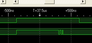
    The logic analyzer output shows what the code is doing. At this zoom level it is hard to see the short enable transisition at -175us in the top graphic. This short enable toggle should be followed by 4 clocks with data at 0 proir to enable going high again to force a reset.  The second graphic is zoomed in around the -140us point on the top graphic so you can see the "clock" and enable. At the -50us mark it goes into a loop where once again 4 clocks are set during each enable low.  This is in effect a continuous reset.

    I have also attached a c file that captures just the compass code and required header files and suggest we just exchange this file going  forward. Importing your entire folder risks corrupting my project files long since cleaned of the very verbose HAL files. I think we can get through this quickly.  Time permitting I would also like to send you a variant based on SPI.

    Compass-CC2430-C.zip
  • Thanks Mr H. I understand little bit of what you are tring to say is add some delay. I am very new to this area and don't know where exactly I should put these delays. For example when I am shiftin bits in and out of the compass throug there  functions shiftin and shiftout should these  delays be put. Should I put a delay of 500 us?

    http://e2e.ti.com/members/1486773/files/msa_5F00_Main.zip.aspx

    Here is the source code as before Please clarify me as to exactly where I should put the delays inside the functions i.e where and how do I need to put these. If you could explain it in more laymans terms that would be great. Thank you once again .

  • Hello Shailesh,

    I have a project to deliver this morning. This afternoon I will send you more details.

  • Take a look at the code. Below you can see the 00 sent for reset between two /EN and the start of measurement 1000b. It is a polling approach and is waiting for a 00001100 to be returned on the MISO/Dout line. Since I do not have a compass it does not get past the while(meas_not_complete).

     I apologize in advance, I should not write code after midnight. The code should work, it has a couple of flaws. I send the start measurement with a 0x08 and it should be 0x80 as you can see below. Also there is a small chance it could return a data ready in  the same byte as the 0x80 which as written would be missed. I do not start polling until the 3rd byte.

    Compass-with-SPI.zip
  • Hi there, I got this project after the OP I though I would attach my effort in case it is useful for anyone else.


    0842.hm55b_driver.zip

  • Hi, I am trying to test out my CC2530 microcontroller by switching the outputs on Port 0. I am programming my own board using the SmartRF05 EB. I am using a variation of the code above.  I have been stepping through it with IAR's debugger and it says that P0SEL = 0x00 and P0DIR = 0xBF when it reaches the line P0 = 0x00. It correctly sets the P0 register low in the debugger, however, using a multimeter I am reading 3.26V on each pin except for P0_1.  Does anyone have any ideas why this doesn't work?

    void main()

    {

    P0SEL &= ~(P0SEL | BIT7 | BIT5 | BIT4 | BIT3 | BIT2| BIT1 | BIT0);
        P0DIR  |=  ( BIT0 | BIT1 | BIT2 | BIT3| BIT4 | BIT5 |  BIT7);                    
    P0 = 0x00;
    }
    
    
    Thanks for any help,
    Katie
  • Hello Katie

    You want P0SEL to be 0 for GPIO AND P0DIR to be 1 for output.

      P0SEL &= 0x00;
      P0DIR |= 0xFF;     
      P0 = 0x00; 


    Check the SmartRF05 EB schematic to be sure there are no conflicts