This thread has been locked.

If you have a related question, please click the "Ask a related question" button in the top right corner. The newly created question will be automatically linked to this question.

Programming CC2650DK using Jlink debugger

Other Parts Discussed in Thread: SEGGER, CC2650, SYSBIOS, CC2538

Hi,

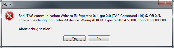
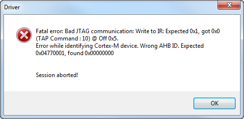
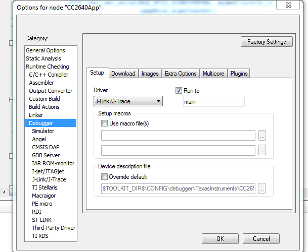
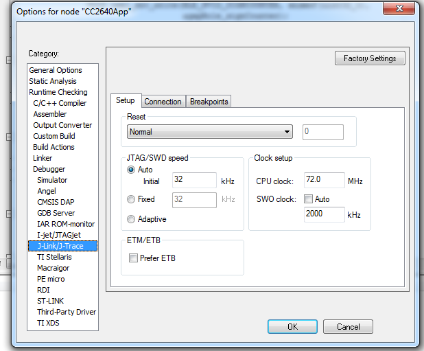
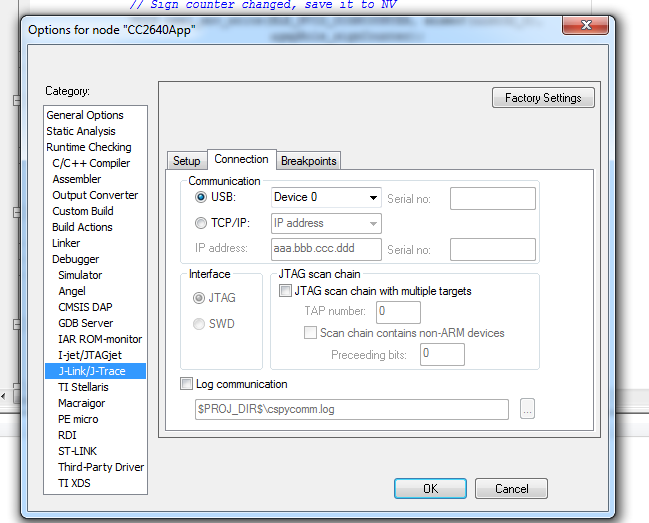
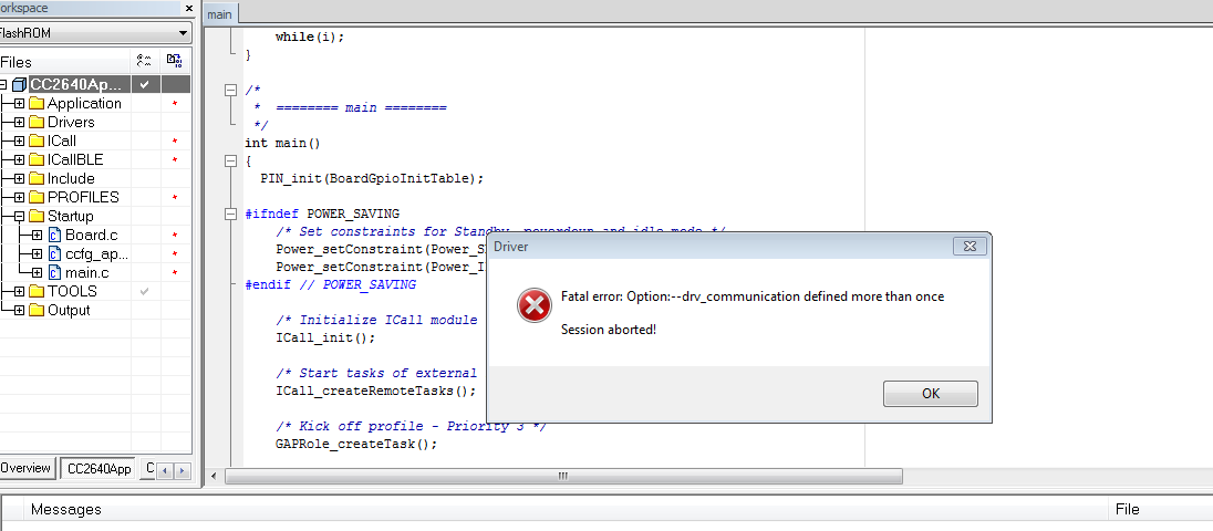
I am having CC2650DK and I want to flash example project using the 10pin JTAG header from IAR . As per the smartRF06 user guide,  I removed the XDS100v3 headers(P408) and connected the  development kit via Jtag debugger. In the debugger options, I changed TI XDS to Jlink/Jtrace . Once the change is made, IAR crashes with the message attached.

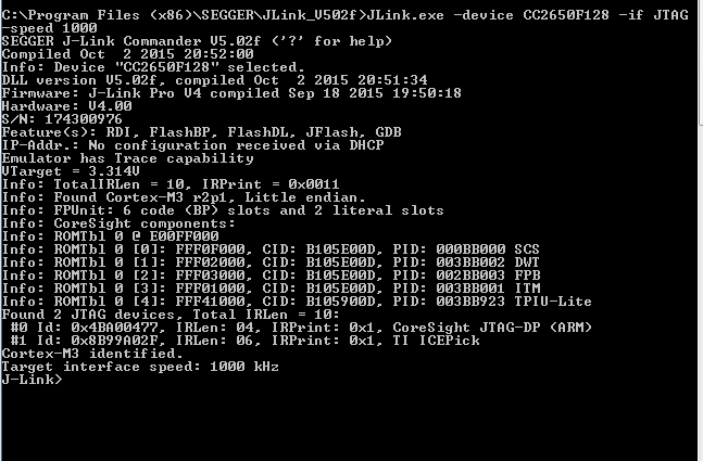
 I tried using Jlink base as well as Jlink Pro. I have installed the latest Jlink segger V502f  driver from the link www.segger.com/jlink-software.html

Can't Jlink be used for flashing to cc2650? what am i doing wrong? Please let me know. 


  • Facing the same issue ,can someone let us know what the issue is?
  • Which version of IAR do you have?

    Regards,
    Bjørn
  • IAR Embedded Workbench for ARM 7.40.3.8938
    IAR Embedded Workbench common components 7.2.4.3784
  • Hi,
    Can you check if the option "drv_communication" is defined under Project -> Options -> Debugger -> Extra Options in your IAR project?

    If it is, you could try remove this option from there and see if that helps.

    Which software and version are trying to download?

    Regards,
    Bjørn
  • Hi,
    I removed "drv_communication" from the project->options->debugger->Extra options. The previous error message is gone.
    I removed the XDS bypass header, connected Jlink EDU and changed debugger to JLINK/JTRACE. Now the message coming is
    "Cannot get CPU status after 4 retries". I tried with and without XDS debugger header. At times the message is "Bad JTAG Communication" "Abort debug session" . Is there anything else which needs to be done?
  • Hi,
    The jumpers on the "XDS100v3 bypass" header should be removed. The J-Link should be connected to the header marked "20 pin ARM JTAG connector" (P409) at the edge of the SmartRF06EB board. Make sure pin 1 on the connector is placed correctly on pin 1 on the header.

    Bjørn
  • Hi,

    I tried connecting the JTAG header to the 20 pin ARM connector with no luck. I am having the segger Jlink adapter having 10 pin and 20 pin connectors. I tried with that too. But still no luck.
    Then according to the forum.segger.com/index.php link I found. I tried erasing the memory using XDS debugger and then changed debugger to Jlink/JTrace. It worked for simple BLE peripheral project. When I repeated the same using SimpleBLEcentral,SimpleBLE broadcaster same issue again started. Why is this ? Any idea? I am planning to use the example projects as my reference for the code I am developing. Will there be any issue? Is it because of something in the code?

    Any precautions which needs to be taken for using JTAG for programming the CC2650 for a custom board? as we are looking forward to use JTAG for the custom board we are developing.
  • Hi,

    You will need to make sure all the JTAG pins + the RESET pin is connected from the device to the JTAG connector. This makes sure that the Halt in Boot functionality on the device can be used by the debugger. The Halt in Boot functionality is used by the debugger to ensure that code is not run when debugger connects that can potentially cause trouble for the debug connection (code that powers down JTAG for example). Halt in Boot shall be supported in the newest JLink drivers.

    Does it work with the other BLE projects if you start with erased flash?


    Bjørn

  • Hi,
    I tried the erase followed by flashing using JLINK. It didn't work. Is there any trivial modification that should be done on the project side?
    Segger JLink is shown as one of the supported debuggers in TI-WiKi. Then why is this happening? XDS is also based on JTAG, right? Has anyone used JLINK for CC2650?
  • Hi,

    I have a simple blinky test project. I'm able to use Segger J-Link + CC2650 with Segger's 5.02f driver, but occasionally I get the below error.


    Power-cycling the CC2650 device seems to fix the issue when it appear. Is this the behaviour you see?

    Edit: I was mistakenly using a malfunctional test device. Using a "normal" production CC2650 device and I do not see this issue.

    Br,
    TIABO

  • Hi,

    I am getting the same one.. I tried a simple blinky project. It didn't work.. I didn't include code related to BLE and Ti_RTOS (BIOS_start).  Just plain pin_Set_output() and a loop for delay in main(). Am i doing something wrong in the code? 

    #include <xdc/runtime/Error.h>

    #include <ti/sysbios/family/arm/cc26xx/Power.h>
    #include <ti/sysbios/BIOS.h>

    #include "ICall.h"
    #include "bcomdef.h"
    #include "peripheral.h"
    #include "simpleBLEPeripheral.h"

    /*To include board related files*/
    #include "Board.h"

    /* Header files required to enable instruction fetch cache */
    #include <inc/hw_memmap.h>
    #include <driverlib/vims.h>

    #ifndef USE_DEFAULT_USER_CFG

    #include "bleUserConfig.h"
    #include <ti/drivers/pin/PINCC26XX.h>

    // BLE user defined configuration
    bleUserCfg_t user0Cfg = BLE_USER_CFG;

    #endif // USE_DEFAULT_USER_CFG
    int LED_STATE=1;

    /**
    * Exception handler
    */
    void exceptionHandler()
    {
    volatile uint8_t i = 1;
    while(i){}
    }

    #ifdef FEATURE_OAD
    #if defined(__IAR_SYSTEMS_ICC__)
    extern uint32_t __vector_table;
    #elif defined (__TI_COMPILER_VERSION__)
    extern uint32_t ti_sysbios_family_arm_m3_Hwi_resetVectors;
    #endif //Compiler
    #endif //FEATURE_OAD

    // for key press
    PIN_State keyPins;
    PIN_Handle hKeyPins;

    void keyCallback(PIN_Handle hPin, PIN_Id pinId); // Callback for button press

    /*
    * ======== main ========
    */
    int main()
    {
    PIN_init(BoardGpioInitTable); // GPIo initialization using BoardGpioInittable where pin mappings are defined


    // Initialize KEY pins. Enable int after callback registered
    hKeyPins = PIN_open(&keyPins, BoardGpioInitTable);
    PIN_registerIntCb(hKeyPins, keyCallback);

    PIN_setConfig(hKeyPins, PIN_BM_IRQ, Board_KEY_UP | PIN_IRQ_NEGEDGE);
    PIN_setConfig(hKeyPins, PINCC26XX_BM_WAKEUP, Board_KEY_UP | PINCC26XX_WAKEUP_NEGEDGE);


    while(1)
    {
    PIN_setOutputValue(hKeyPins,Board_LED1,true);
    for(int i=0;i<100000;i++)
    for(int k=0;k<10000;k++);
    PIN_setOutputValue(hKeyPins,Board_LED1,false);
    for(int i=0;i<100000;i++)
    for(int k=0;k<10000;k++);
    }

    return 0;
    }

  • Can you share screenshots of your IAR project settings? Project > Options > Debugger, and Project > Options > Debugger > JLink.

    Edit: I've attached my simple blink led for IAR 7.40.3 + CC2650. Select the "Jlink" build configuration.20151022_cc26x0_blink_led_ewarm7_40_3.zip

  • Hi,

    I am attaching the screen shots of the project

    .

  • Do you observe the same issues with the blinky project I attached?
  • Hi,

    It worked. In the first attempt it didn't work. Then I flashed first using XDS and then JLINK. It worked.. Even after power cycle reset, it works via JLINK.  I  am using the example project itself from TI/simplelink/  folder. Why is it so? I could flash the GPIO project which was not working earlier now by JLINK. But the SImpleBLEperipheral stopped flashing via JLINK.. 

  • Hi,

    I am having 4XS,5XD and 7ID modules of CC2650 and the smartRF06EVB. Till yesterday I was using 7ID, but for the final board we are planning for 5XS. So I replaced the 7ID with 5XS and was flashing simpleBLEperipheral project using XDS. I had kept breakpoints in between but it didn't hit the breakpoints I had kept in GAP_Task for simpleBLEperipheral example project. But all the breakpoints were hit while using 7ID. Is there anything which needs to be done before using 5XD??

    We played around with the R15 and R16 resistors, but no luck..
  • Which Jlink + target + project combination is not working, and which is working for you?

    If you have a project that is working with J-Link, please compare the IAR project settings for the debugger with the non-working one.
  • Hi all,

    My name is Erik and I am a member of the J-Link development team.

    We, the SEGGER J-Link team, are not aware of any issues with CC2650 in the latest version (5.02f) of the J-Link DLL. We just gave the "simple blinky test project", TIABO posted below a quick try and it is working just fine here on the evaluation board. We have been in contact with TI regarding this project and they can confirm that it is working on their side as well. The error in the TIABO's post was related to an hardware setup issue.

    Do you see any issues using this project, too? If not, it seems to us that the issue is related to the project configuration.
    For the case you see any issues, can you please download the J-Link software package and start the J-Link Commander (JLink.exe) with the command line options as below and upload a screenshot of the entire J-Link Commander output?
    JLink.exe -device CC2650F128 -if JTAG -speed 1000


    Best regards
    Erik
  • Hi,

    I am having two setups,

    7ID module attached to smartRF06EVB
    5XD module attached to smartRF06EVB.


    I was using 7ID with smartRF06EVB for the last few days. The project TIABO gave me works with JLINK. The same project settings were made for other sample projects like simpleBLE peripheral, broadcaster etc. The JLINK settings of 1000KHz initial speed and 72MHz CPU speed. It works with JLINK at times. But the stability with which XDS works is not there. Why is it so?

    I have few more doubts too, With the code TIABO gave I tried blinking an LED using 5XD module and smartRF06EVB. I changed the DIO configurations and got it working. I had previously attempted simpleBLE peripheral using 5XD and it didn't work which confused me. Is there any configuration which needs to be done when switching between packages?

    In another post, regarding pin mapping, experts mentioned that any GPIO pin can be configured as SPI/ I2C etc? Is it so? Is there any way to verify the pin mapping ?

    As per board.h of 5XD module, DIO_2 and DIO_3 of 5XD is mapped to two on board LEDs. Of which only one worked. The other two is shown as pin unassigned. Is there some other change that must be done?
  • Hi Annamol,

    I'm not sure I understand the question. What are you trying to do?

    If this is a separate issue not related to Jlink debugger, can you post it as a new thread, and explain more exactly what the problem with the different package sizes and pins are? This way it's easier for others to find the question and solution as well, and it's easier for us to notice a new question.

    Best regards,
    Aslak
  • Hi,
    Sorry for the confusion. I will move it to a new post. The issue with JLINK debugger is still there. With XDS at any time, any module can be flashed. As per the previous posts, I changed the configurations of the project I was using to the one working with JLINK debugger. I don't know the reason behind this weird behavior of JLINK debugger. It flashes at times without issue. Out of 5 attempts, 2 times it will work. Again if I flash the same project within minutes to confirm it is working, It won't flash and will throw the same error.

    Why is it so?
  • Is it possible for you to share the project you are using, in order for us to reproduce it? If you don't want to share it in the thread, add me as a friend and send me a message with the project.

    TIABO
  • Hi,

    I have shared the dropbox link. Hope that is enough. The sample project I am working with simpleBLEperipheral from the example folder.  I tried attching it as a zip folder. It failed because of the size constraints

  • Hi,
    Any luck??
  • Are you using version 2.1.0 of the BLE stack, found at www.ti.com/.../ble-stack
  • I'm able to reproduce this on my side. Now that I can reproduce this, I will follow up with Segger to try to figure out why this is happening.

    TIABO
  • Hope to get a positive response from their side
  • I've provided them with detailed steps on how to reproduce the issue and are looking into it.

    TIABO

  • I test 20151022_cc26x0_blink_led_ewarm7_40_3.zip with my jlink EDU with CC2650DK from IAR 7.40.5 but I get the following error:

    Fri Oct 28, 2016 16:56:21: Fatal error: CC2538 (connect):Can not find ICE-Pick (IDCODE mismatch). Expected 0x0B00002F, found: 0x00000000 Session aborted!

    I don't know why it shows CC2538 but actually I use CC2650. Anyway, I cannot use jlink as debugger to my CC2650. Can you help?
  • I solve the issue by downloading and install J-Link Software and Documentation pack for Windows.