This thread has been locked.

If you have a related question, please click the "Ask a related question" button in the top right corner. The newly created question will be automatically linked to this question.

NFC chip with power amplifier.

Other Parts Discussed in Thread: RF430FRL152H, RF430FRL152HEVM

hello,

I am trying to attach a power amplifier to the NFC chip s 
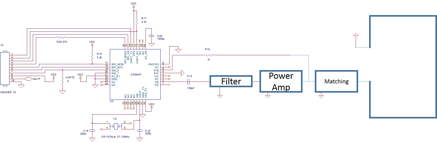
o I could read out from distance (~30cm).
Without power amplifer, I could read data but it could not with power amplifier.

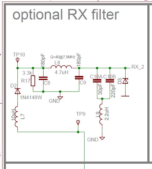
Here is the circuit and block diagram I designed.
Would anyone could comment what I am doing wrong?

For now, I use CR95HF as a reader and RF430FRL152H for transponder. It seems reader sends data to transponder but does not receive data.

Output power is high enough: ~8W.
I can see perfect sinusoidal waveform at the antenna but when it was attached to RX pin, it is a little distorted.

Thank you in advance.

  • Hello SeugnMin,

    Before providing recommendations I have a few questions to better understand your application:

    1. Have you tried presenting the RF430FRL152H closer than 30 cm to the reader and check if the reader can successfully read the transponder? If yes, what is the farthest distance you can read the transponder from?

    2. Is the RF430FRL152H battery powered or RF field powered? (Battery powered will have longer range performance)

    3. What are the dimensions of the antenna of the RF430FRL152H's and  of the CR95HF reader?

    4. What are the tunning values used for the RF430FRL152H?

    5. Can the output power of the CR95HF reader be reduced?

    Best regards,

    Erick

  • Also, have a look at the attached read ranges with some of our Tag-it HF-I ISO 15693 tags using various output power readers.  The range of a battery powered RF430FRL152H device will be about the same.  If you are harvesting energy for other purposes as well, the range will be reduced.  These are all "off-the-shelf" type readers from Feig Electronic.  Please note that a 300mm x 300mm antenna was used for all of these tests.  If you have 8W output power, the problem could be that you are also saturating the receiver on your reader as that is a lot of power and proper filtering must be used.     TI HF Reader and HF Tag Read_Ranges.pdf

  • Thank you for your reply. Here are my answers.

    1. Have you tried presenting the RF430FRL152H closer than 30 cm to the reader and check if the reader can successfully read the transponder? If yes, what is the farthest distance you can read the transponder from?

    Yes, I am testing with 0cm apart but no data comes in. without PA, it works well at 0cm. 

    2. Is the RF430FRL152H battery powered or RF field powered? (Battery powered will have longer range performance)

    It is not battery powered but RF430FRL152H receives enough power. 

    3. What are the dimensions of the antenna of the RF430FRL152H's and of the CR95HF reader?

    I used RF430FRL152HEVM module and 23X23cm antenna was used for CR95HF.

    4. What are the tunning values used for the RF430FRL152H?

    Not sure exact numbers but it is highly well-tuned as it is evaluation board.

    5. Can the output power of the CR95HF reader be reduced?

    Yes, I tried several output powers from 1-8W. 

    I believe this is definitely hardware configuration problem from the reader. 

    CR95HF uses two TX and RX pins each (TX1, TX2, RX1, RX2) but I am using only one pin. 

    Also there would be phase delay...but I am not sure it will matter. 


  • Thanks, Eddie.
    The receiver is not saturated as R13 limits the voltage at RX pin. Also various output power have been applied and tested -> did not work.
  • i found your post here too - they are the same, correct?

    in looking at ST's app note on their EMI filtering and tuning, i saw that you must limit the RX voltage to below 7V, you said you were handling that correctly - so anyway here is that link ==>

    looks like normally it wants to see about 4V nominally - in your case i would say that since you are implementing only one half of what you could do here, you do need to do all the math and so forth to filter and impedance match the output and the RX input.

    maybe you could get away with putting fast schottky on the RX in pin to knock down the signal instead of using a resistor and follow that with a bandpass filter.

    something like this topology perhaps (where the RX2 net would be input to the device you are using as transceiver - adjust values to what your circuit will be using. you may also just as a course of action go ahead and replace or try another transceiver IC in case you have blown that out. and also, make sure you are setting the modulation depth i think here to 100% with the amp and try using ASK and FSK settings for the uplink back from the tag in case using teh FSK method is helping you with whatever noise problem you have induced here. 

    its hard to see exactly what you are doing with just the block diagram. 

  • Hello can contact me to Skype  e have the same problem .my Skype  is slotcardreadee tx or mail slotcardreader@gmail.com