This thread has been locked.

If you have a related question, please click the "Ask a related question" button in the top right corner. The newly created question will be automatically linked to this question.

problem about the crystal of TRF7960ATB

Other Parts Discussed in Thread: TRF7960, MSP430F5529

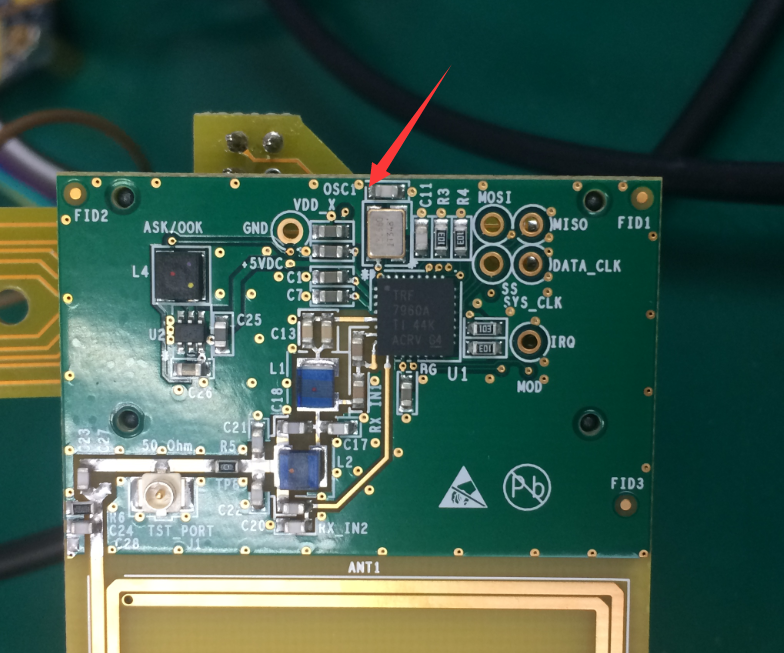
I bought a TRF7960ATB board to test.

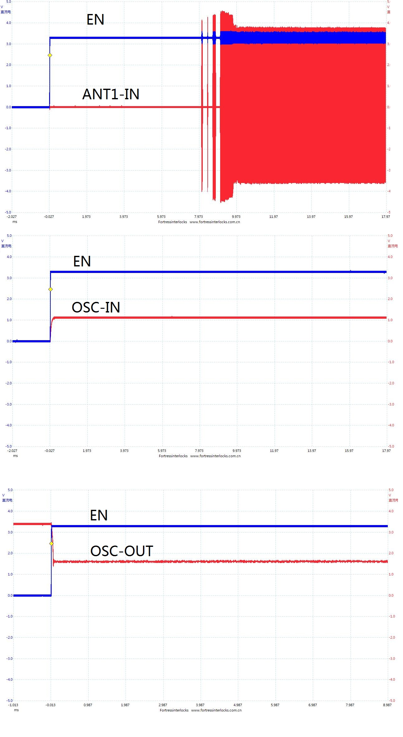
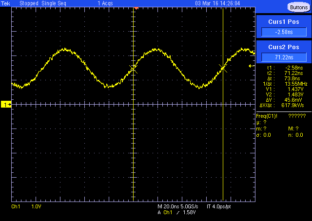
And there is a problem: The signal of the crystal is about 1.1VDC and 1.7VDC, I am not sure it is broken by the ESD. But I can find the 13.56MHz signla on the antenna, as the picture.

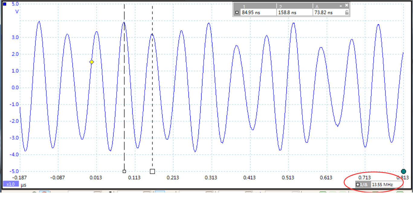
Why did it like this? Did the DC signal on the crystal is right?

  • not sure what your scope probe coupling is or where your trigger is - can you zoom out first and check this condition? 

    are you having some issue with the unit which led you to start troubleshooting with test equipment?

    which MCU are you using? do you have schematic connection and also any picture of what you have connected/wired up? 

  • HI Josh,

    1. the MCU is STM32, when I found that there is no data on the MISO, so i check the TRF7960ATB, and found there is something wrong on the OSC pin of TRF7960.

    2. I update 3 pictures as follow, show the EN and OSC and ANT1-IN

    3.I conneted the TRF7960ATB with mcu by VIN(3.3V)/GND, MOSI,MISO, CLK, EN, EN2, SS

    4.I had test the board just with the VCC/GND and the EN, the result is the same.

  • something is incorrect about the way you are measuring the clock, as you see the TX come on, this is impossible unless the crystal is up and running prior to that.

    are you having some issue which led you to troubleshooting this with test equipment?
  •  I checked it again, by measure the clock on the PIN of the crystal and the capacitor, it is the same.

    sorry, I didn't get what does "are you having some issue which led you to troubleshooting this with test equipment?" mean, I am a chinese.

  • the question of course has no root in where you are from.
    the question is asking if you have an issue with the NFC or HF RFID operations that led you to looking at this hardware with test equipment.
    if you are still gettting same results, then you are still doing something wrong. only way for me to help you now is if you take a picture of what you are doing so i can see what to tell you to change.
  • I mean I am a chinese, my English is not very good, so I didn't understand what is that sentence mean. now I am clear.

    when I try compile the software, I found there is no data on  MISO, but CLK and MOSI is right, so I trend to check the OSC of TRF7960, and found there is no data on OSC pin.

    my probe was test on the pin of the capacitor, as the arrow show in the picture.

    I don't have cadence to open the BRD files of this board, could you provide the gerber files by PDF, please?

  • ok - well your writing is OK to me :)

    anyway -

    here are the Gerbers in PDF format

    TRF7960ATB_BRD.pdf

    TRF7960ATB_ASSY1.pdf

    TRF7960ATB_ASSY2.pdf

    TRF7960ATB_FAB.pdf

  • thanks for the files. I checked it and sure the pin I probed is right, and now I can find data on the MISO line, but the OSC_IN pin is still no wave, what's wrong? my probe stop the crystal work? but if so, why the IC could work without crystal work?

  • maybe your ground is a loop or something - i just went and measured it on -ATB board, using MSP430F5529 EXP board as base. 

    here is the capture, measured from same exact spot you are. 

    after this i had a thought, can you check that the regulator on your board has a CKT on top marking and not CKR?

    thanks

  • I think my ground is right,because the test result on other point all are right.

    the top marking of the regulator is CKT,.

  • ok, then move on, please - i cannot duplicate or explain it and since your TX is coming on, i think your clock is OK, despite your trouble measuring it. If you have other issue, please let us know.