This thread has been locked.

If you have a related question, please click the "Ask a related question" button in the top right corner. The newly created question will be automatically linked to this question.

Could you help test RF performance( spurious emission) for CC2650 plus PA?

Other Parts Discussed in Thread: CC2650

Hi, 

One of my customer want to develop with CC2650 plus PA  for proprietary protocol.

They already test the RF performance with CC2650 Launchpad. One of the parameter they now have concern is  spurious emission.

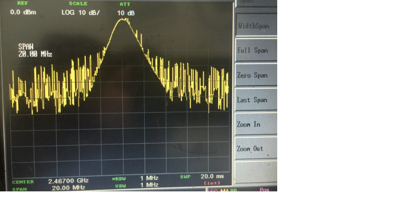
Picture about is the test result with 2650 LP.

Mode is MAXHOLD, freq is 2.467G, bandwidth is 1M, TX power is 0dbm.   We could get the information that  spurious emission is quite high.

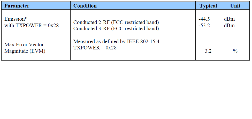
Customer will add in PA to make output power over 17dbm, signal of 2650 should be amplified over 20bB, as well  spurious emission should be amplified over 20dB. So they consider that if it could pass the certification which require  spurious emission < -30dbm.

As we do not have any EVM with C2650 + PA now, could you help test if you have on hand? Thanks!

Vivian

  • Hi Vivian,

    Please refer to this TI-Design for test results: www.ti.com/.../TIDC-CC2650-CC2592-EMK

    Cheers,
    Fredrik
  • Hi, Fredrik:
    Customer wants to test the RF performance before kick off the project? Could you kindly share the reference board to local team?
    For it's an urgency test and could influence whether we could design in. Thanks!

    Vivian
  • Hi Vivian,

    We cannot share that board. All the results are anyway documented in the TI Design document.

    Best regards,
    Fredrik

  • Vivian, 

    The spurs on that image are caused by the PA ramp being two fast, this is the default configuration. You will need to add a patch that enables controlled PA ramping feature of the CC2650.

    Regards,
    /TA

  • Hi, TA:

    Thanks for your information , could you share me the link of patch? Thanks!

    BTW, I send the test result of CC2650+2592 from TI reference design to customer, the still have some concern and need your answer:

    1. in *, it shows that all the test result is with RF shield and is required in FCC test. So any difference of the result with or without shield?

    2. For the Emission performance, customer's criterion is  Emission < -30 dBm when TXpower > 20 dbm.  From the table , it seems that CC2650 + 2592 could easily meet the requirement, I just want to make sure if there's some misunderstanding here.

    Vivian

  • Hello Vivian,

    I cannot see the image from your post. However, the answer is yes, this design requires RF shield to pass FCC requirement.
    Testing for harmonics and spurs was done using CW signal (which is the worst case condition under most circumstances) and we are able to meet the emission requirements for FCC with this test condition. The spurs that are seen on the spectrum analyzer capture from your first post are due to ramping of PA when transmitting packets. If the customer and/or FCC test house insist on testing with packets, the patch that TA mentioned needs to be used to increase PA ramp time. This is the RFE patch "rf_patch_rfe_gfsk" in the latest release of TI RTOS should be applied.

    Also, the latest release of TI RTOS also has an example for proprietary mode implementation on CC26xx which includes this patch. This can be used a as a reference.

    Regards,
  • Hi,

    Thanks for the reply.

    The image I want to post as followed:

    I searched the patch in latest RTOS, what I could find out closest to  "rf_patch_rfe_gfsk" is " "rf_patch_rfe_genfsk.h". Is that the right one you mentioned?

    BTW, which example is for proprietary mode? I could not make sure about it.

    Vivian

  • Hello Vivian,

    The numbers on the table from your post are from conducted measurements. There is no need for RF shield for conducted measurements. However, shield is required to pass radiated tests.

    Yes, that is the correct patch ( At this location by default, C:\ti\tirtos_cc13xx_cc26xx_2_21_00_06\products\cc26xxware_2_24_03_17272\rf_patches). The example can be found under TI RTOS Examples -> Board type (CC2650DK_7ID) ->RF Examples -> RF packet error rate test on IAR and corresponding path on CCS as well.

    Regards,